
Convex C2 Supercomputers - 2017 acquisition from Andreas Holz
Acquisition
| Type: | Acquisition |
| Acquisition date: | 2017-06-26 |
| Acquisition source: | Andreas Holz |
| Acquisition year: | 2017 |
| Gift?: | no |
| Acquisition root: | Acquisitions |
Curated from 4 legacy acquisition articles.
2017-06-26 - Convex C2 Gallery
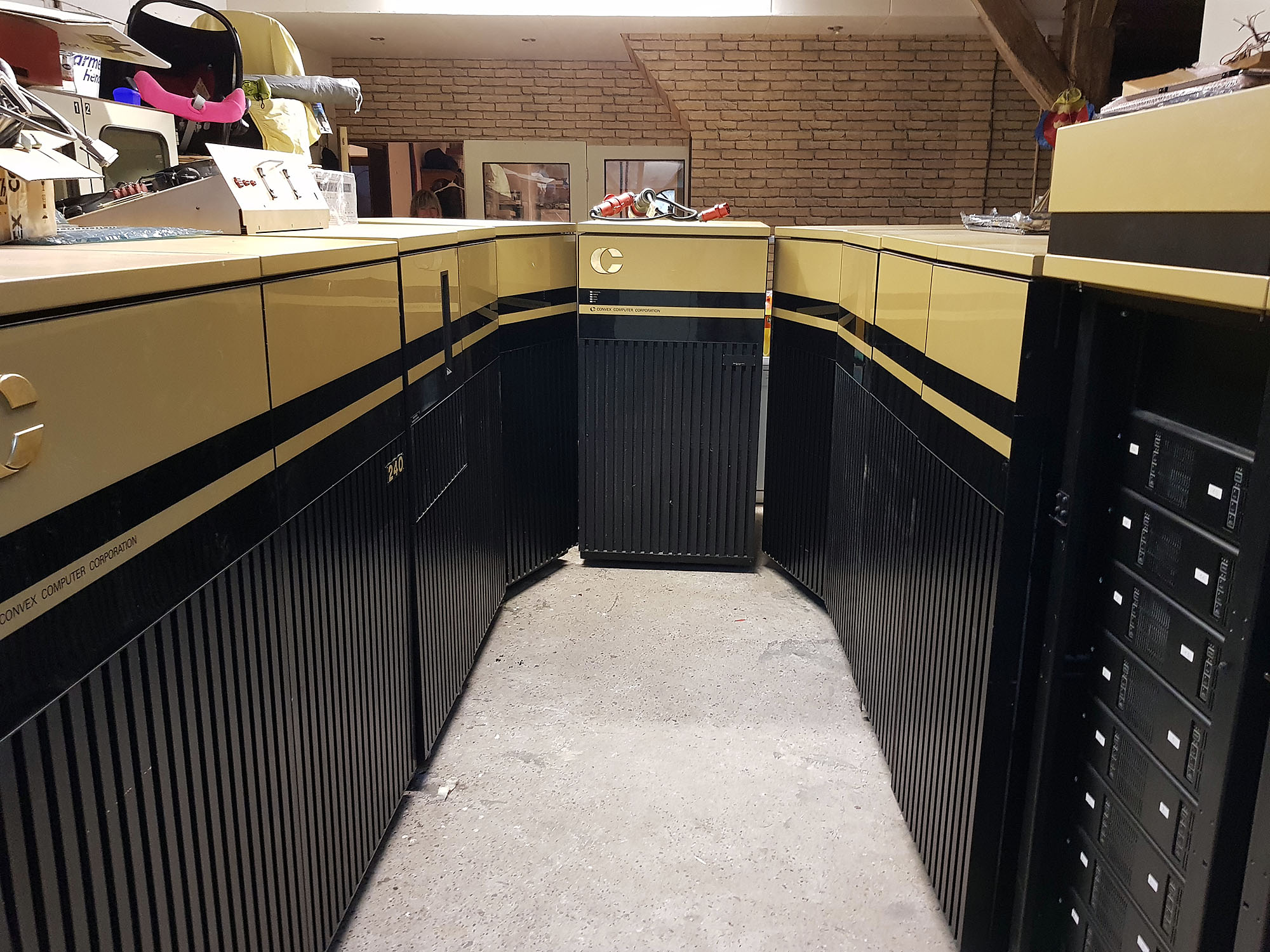
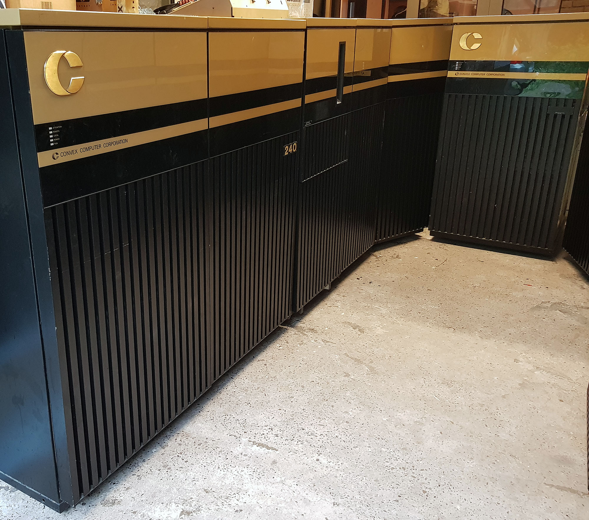
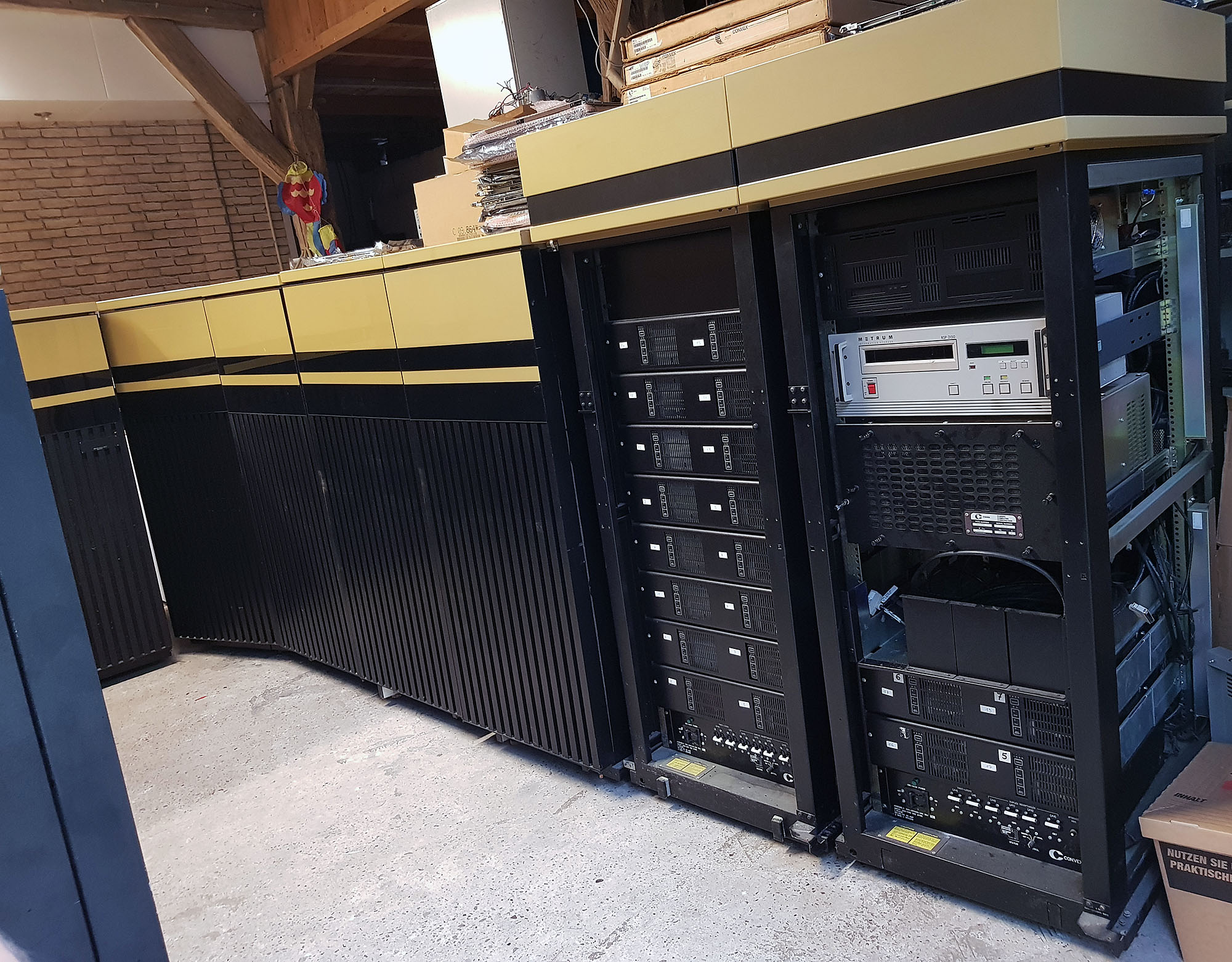
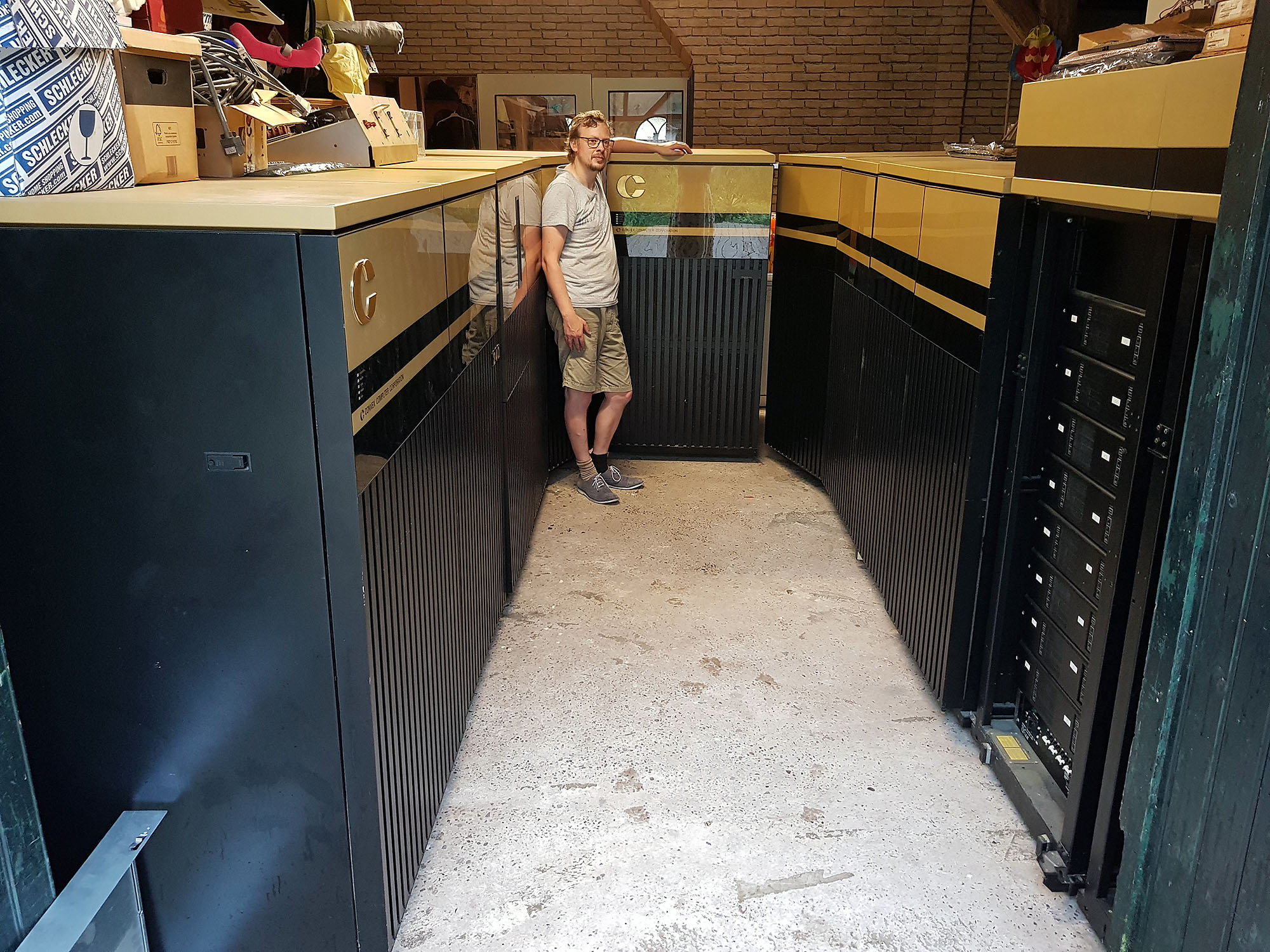
After I got my Convex C1 Supercomputers, I've been contacted by people offering Convex systems and parts to me. Today, I've come to an agreement to acquire a couple of Convex C2 Supercomputers.
After I got my Convex C1 Supercomputers, I've been contacted by people offering Convex systems and parts to me. Today, I've come to an agreement to acquire a couple of Convex C2 Supercomputers.
We need to finalize some arrangements (such as setting the dates), but if all goes well, I'll soon house a 2-cpu Convex C220 and a 4-cpu Convex C240!
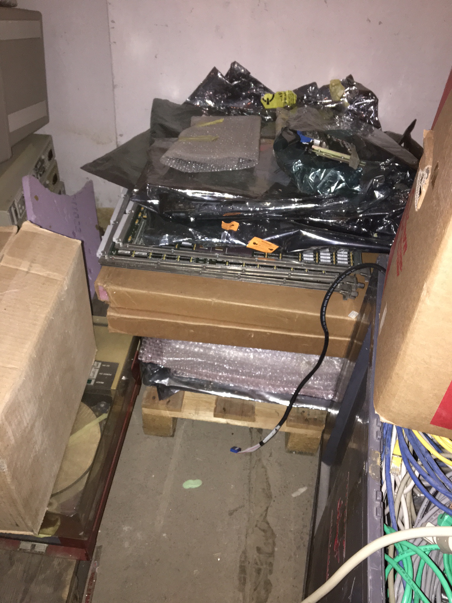
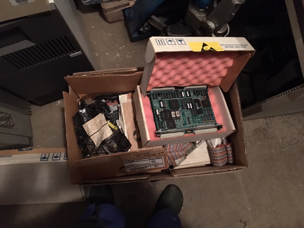
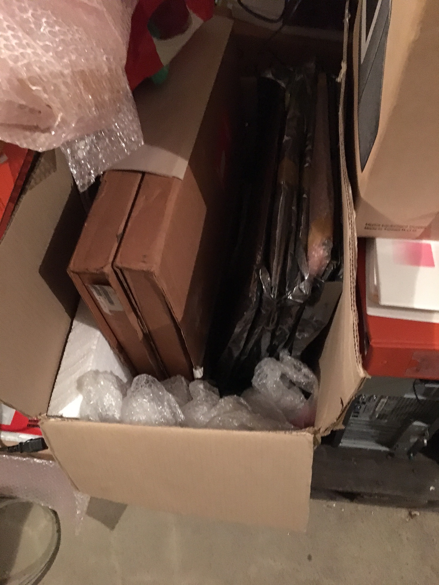
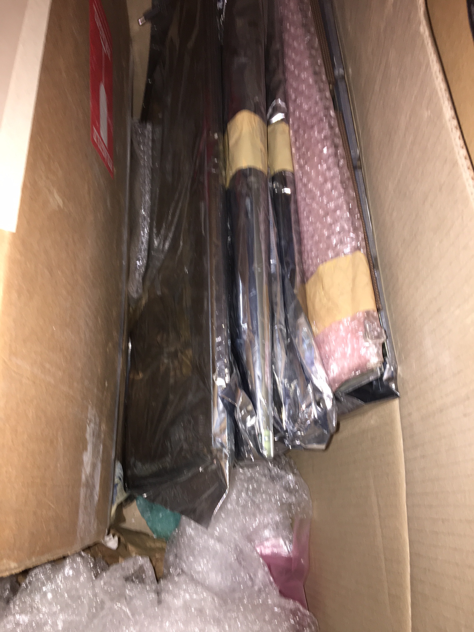
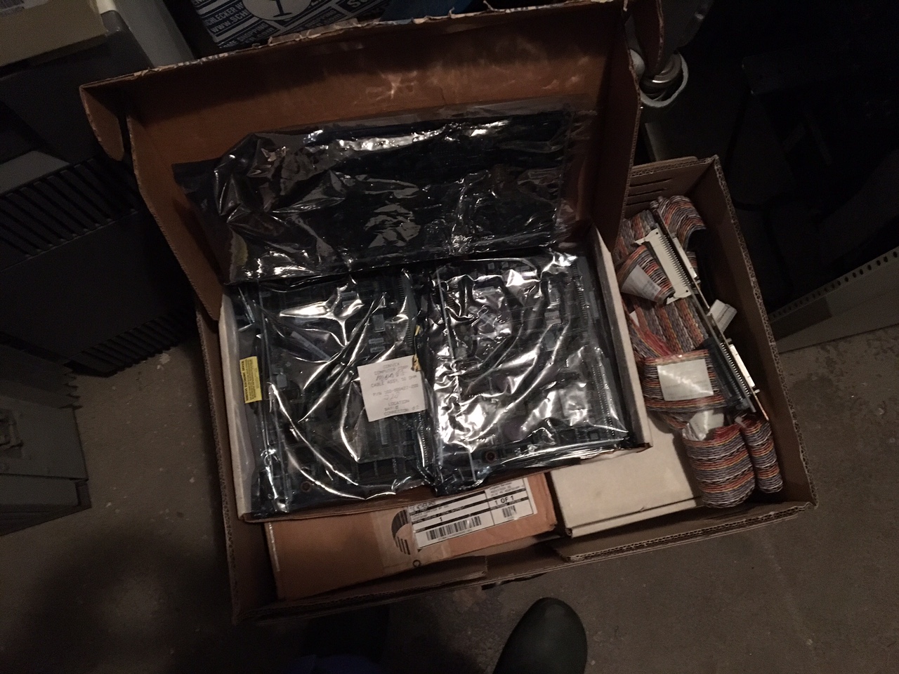
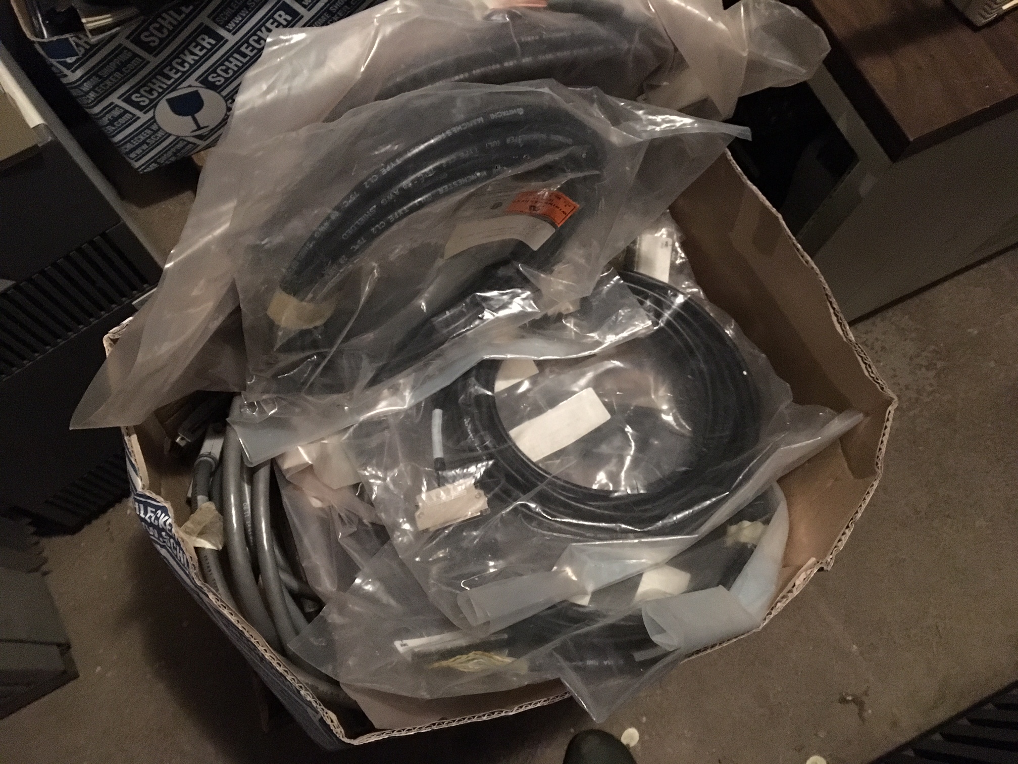
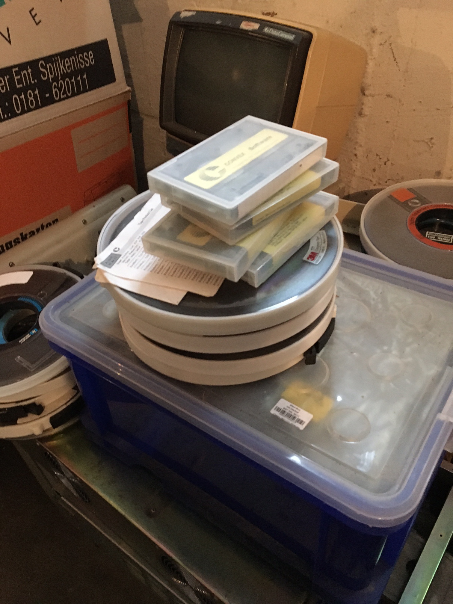
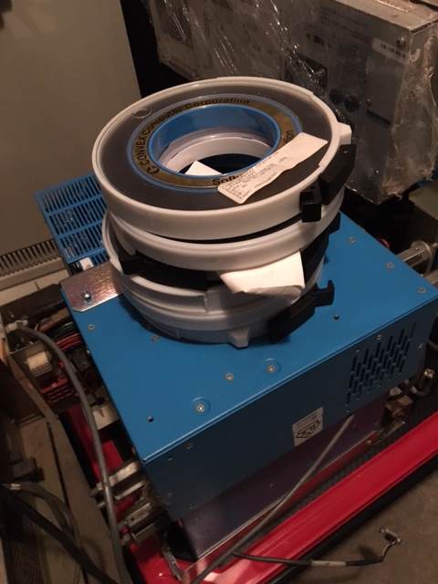
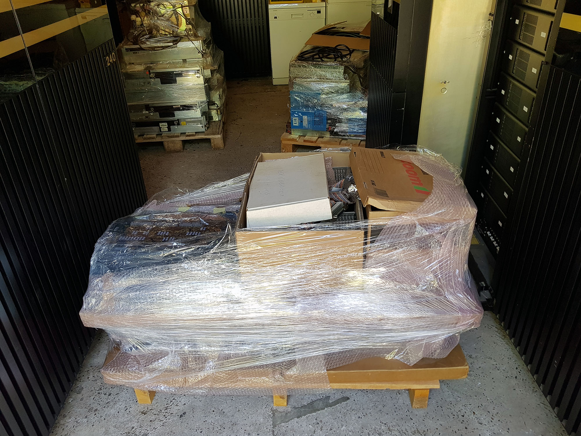
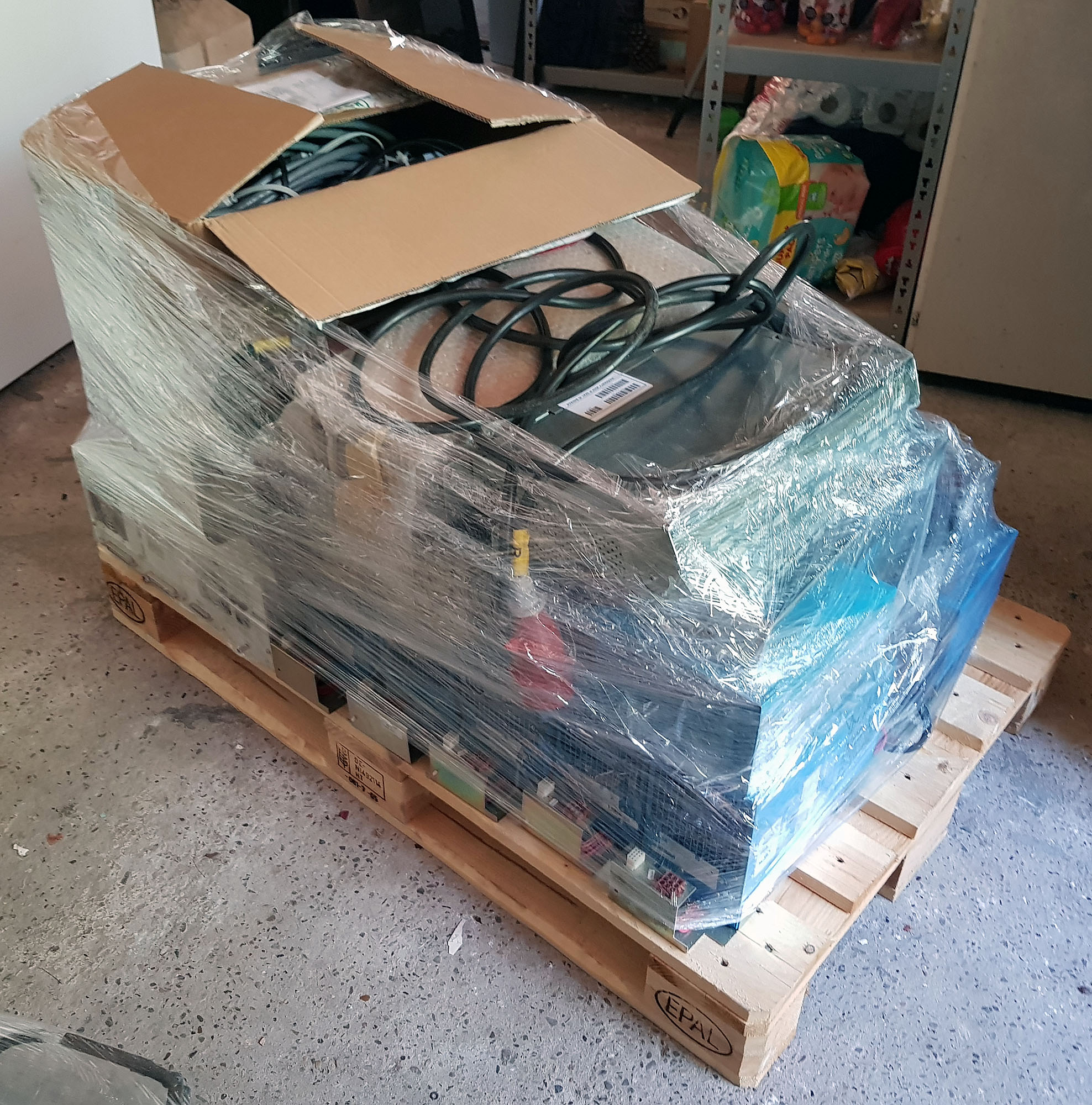
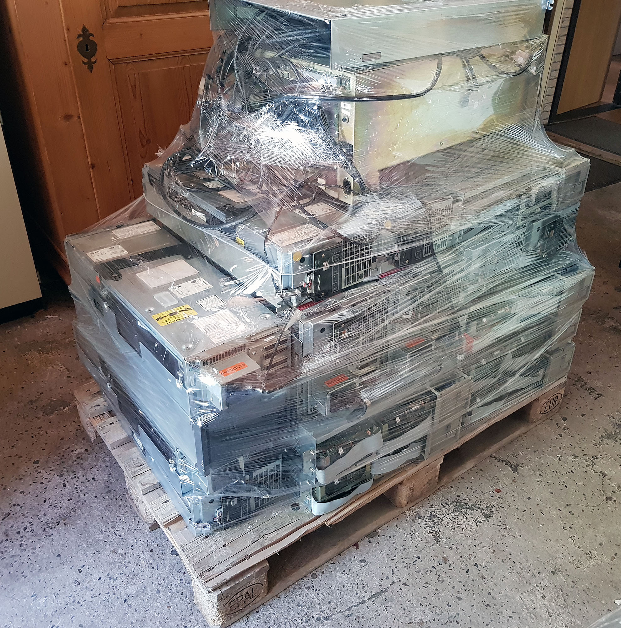
In addition to the CPU cabinets, there are a total of 9 auxiliary racks, with VME crates, hard disks, a 9-track tape drive, and a Metrum tape drive, as well as spare parts (cpu modules, VME modules, power supplies, disks, tape drives, cables), manuals, and software. With these parts, just maybe, I might be able to get my Convex C1 XP running as well!
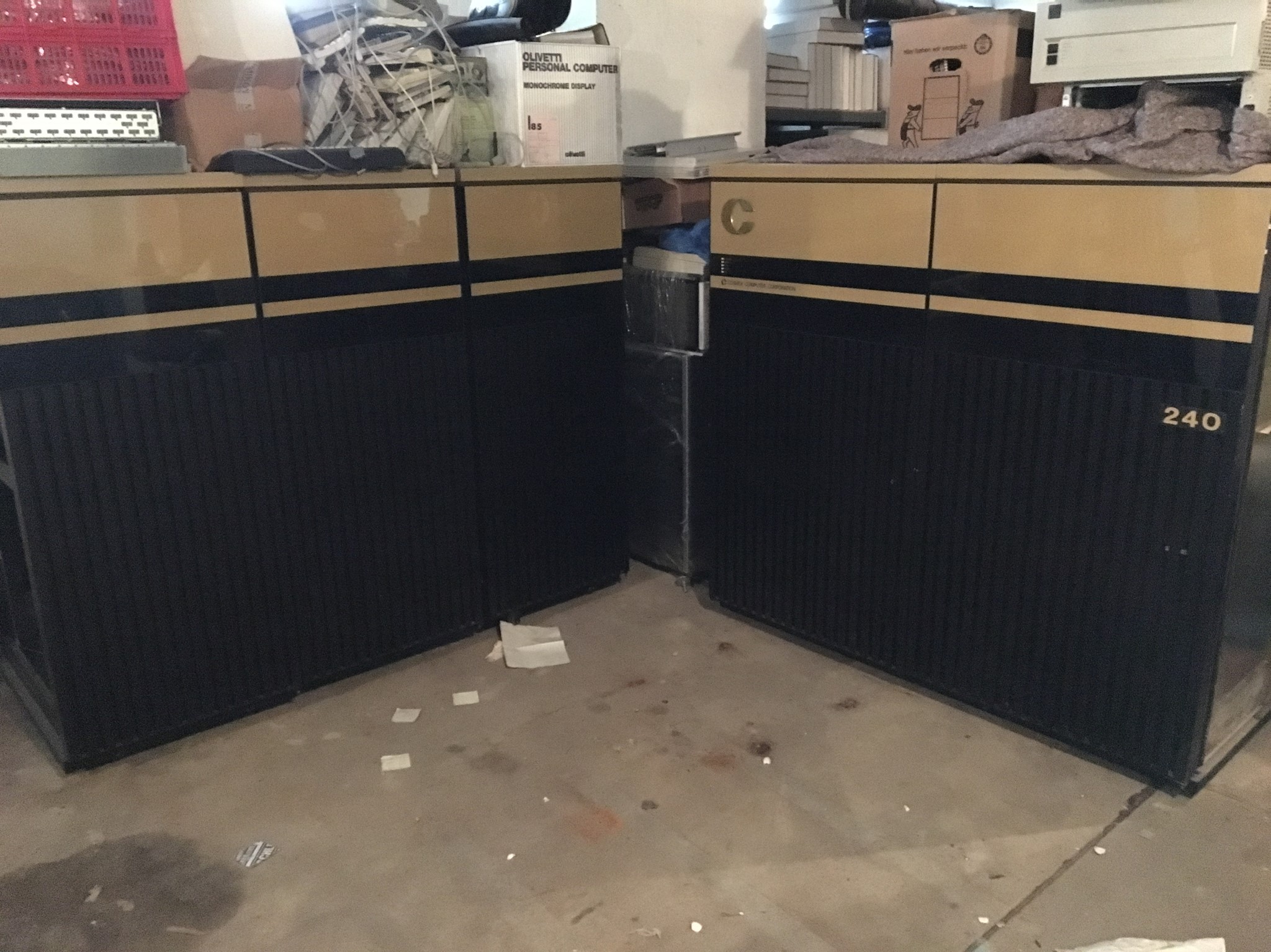
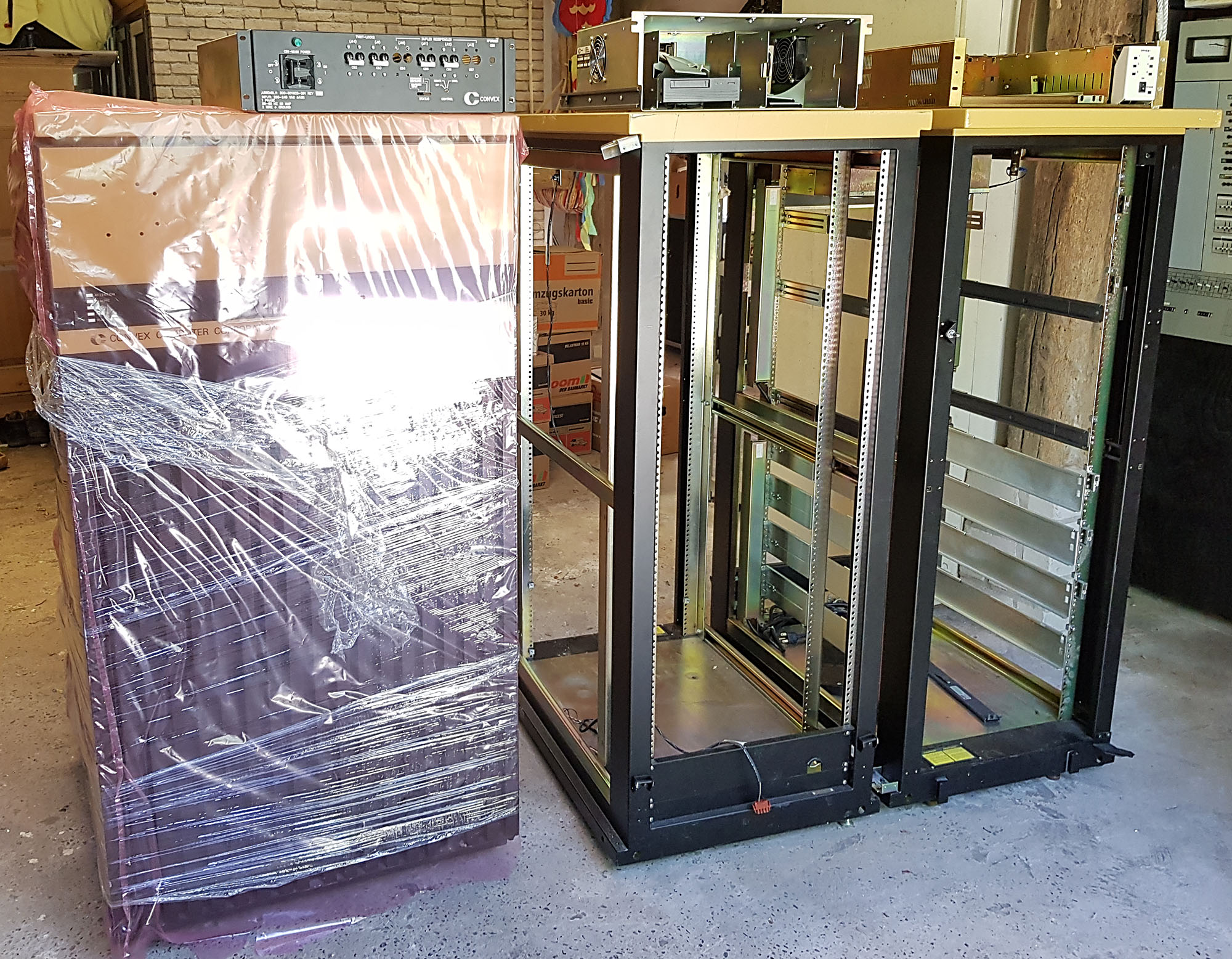
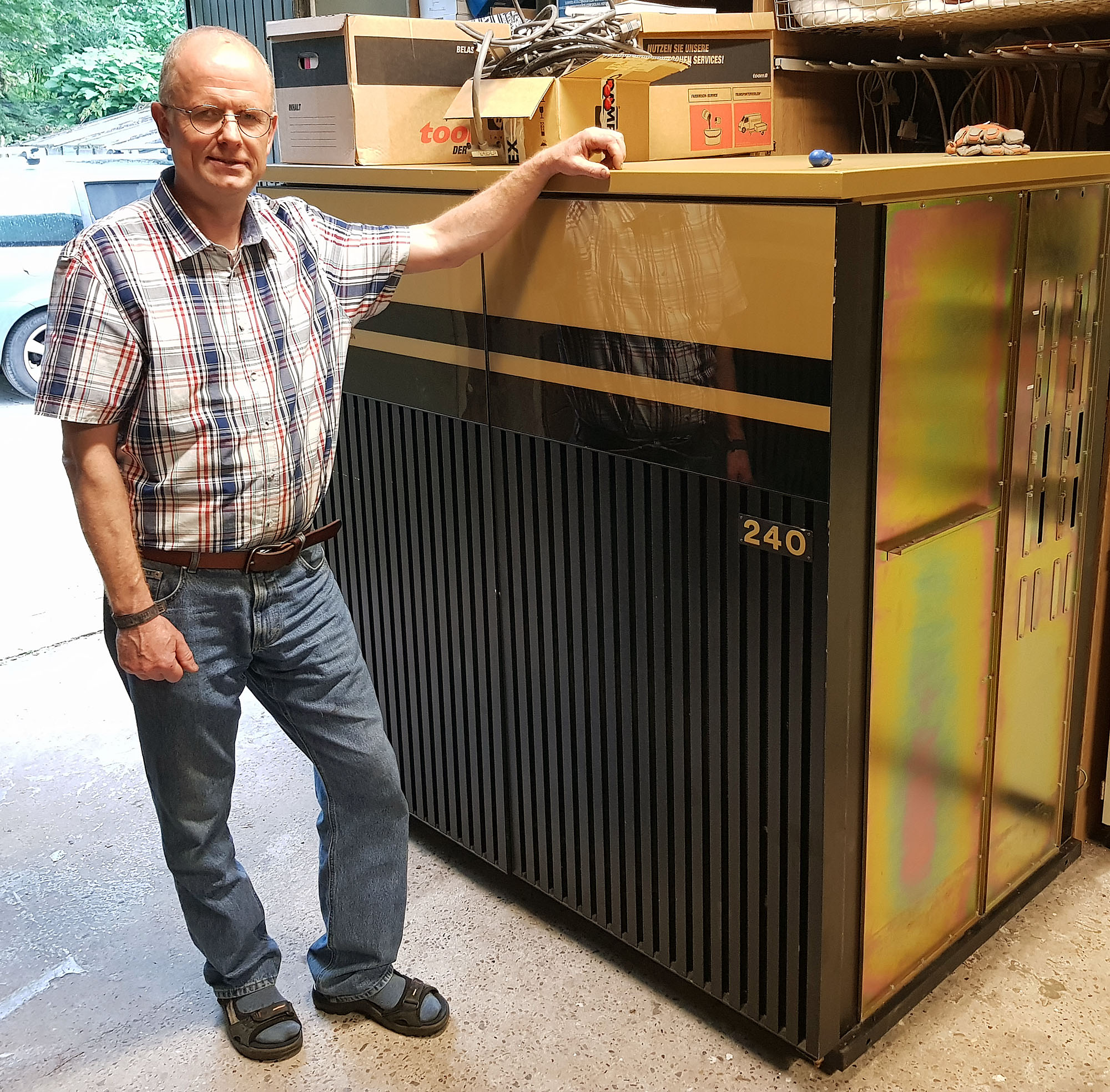
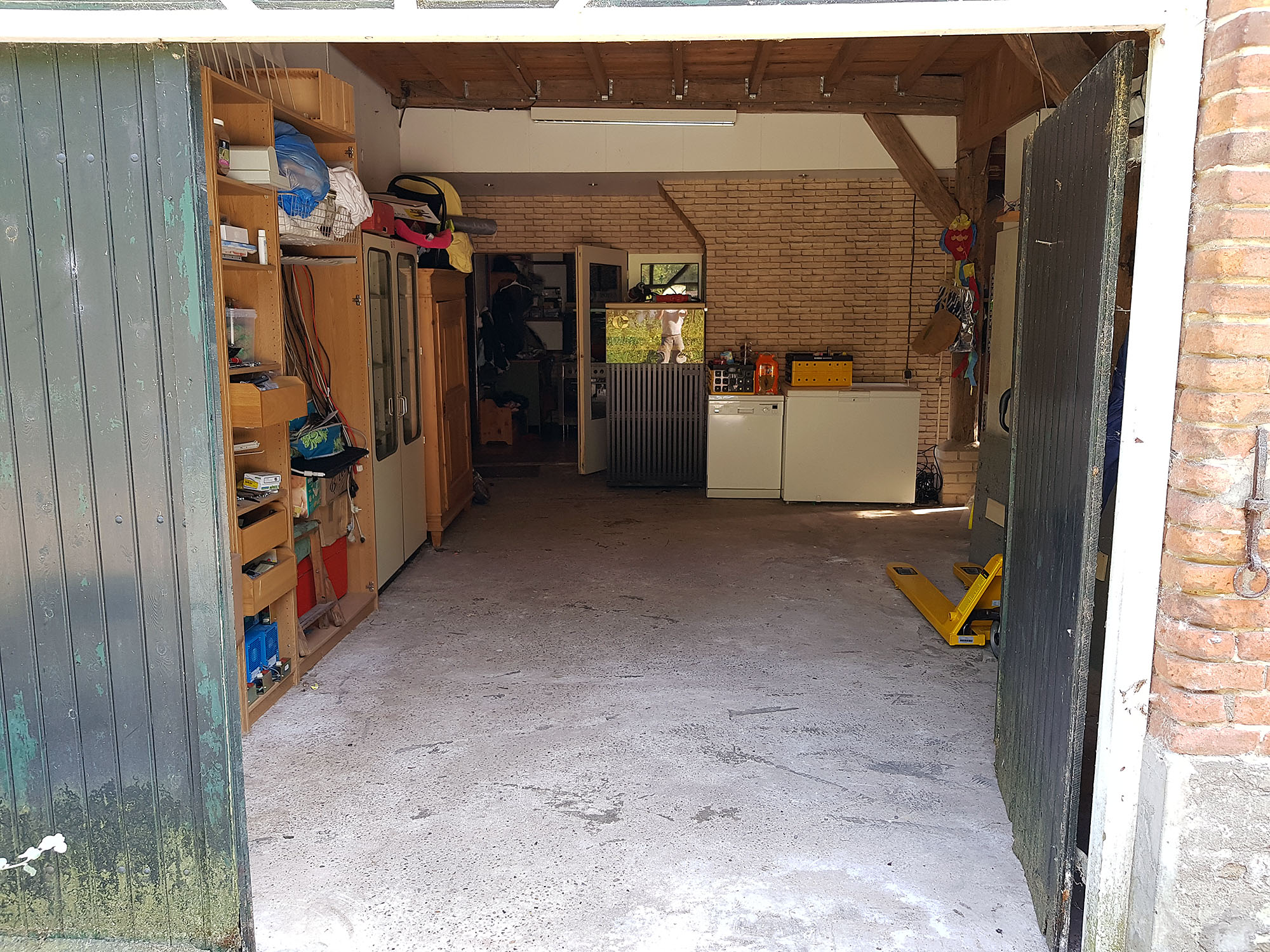
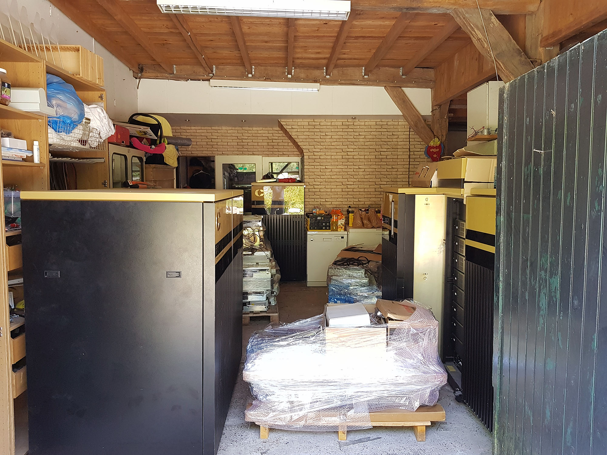
For now, some photos taken by the current owner to keep you happy (I know that seeing them made me very happy):
Acq C2 1

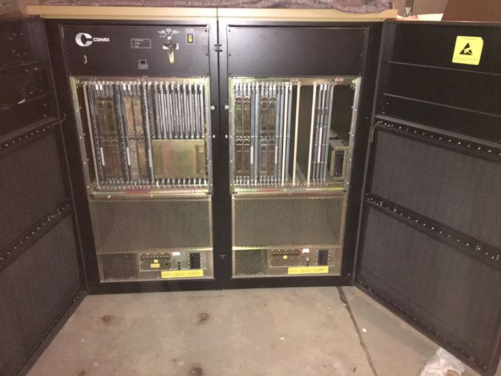

By the way, I hope I've already told you that I have an amazing wife who's willing to put up with things like this coming in!
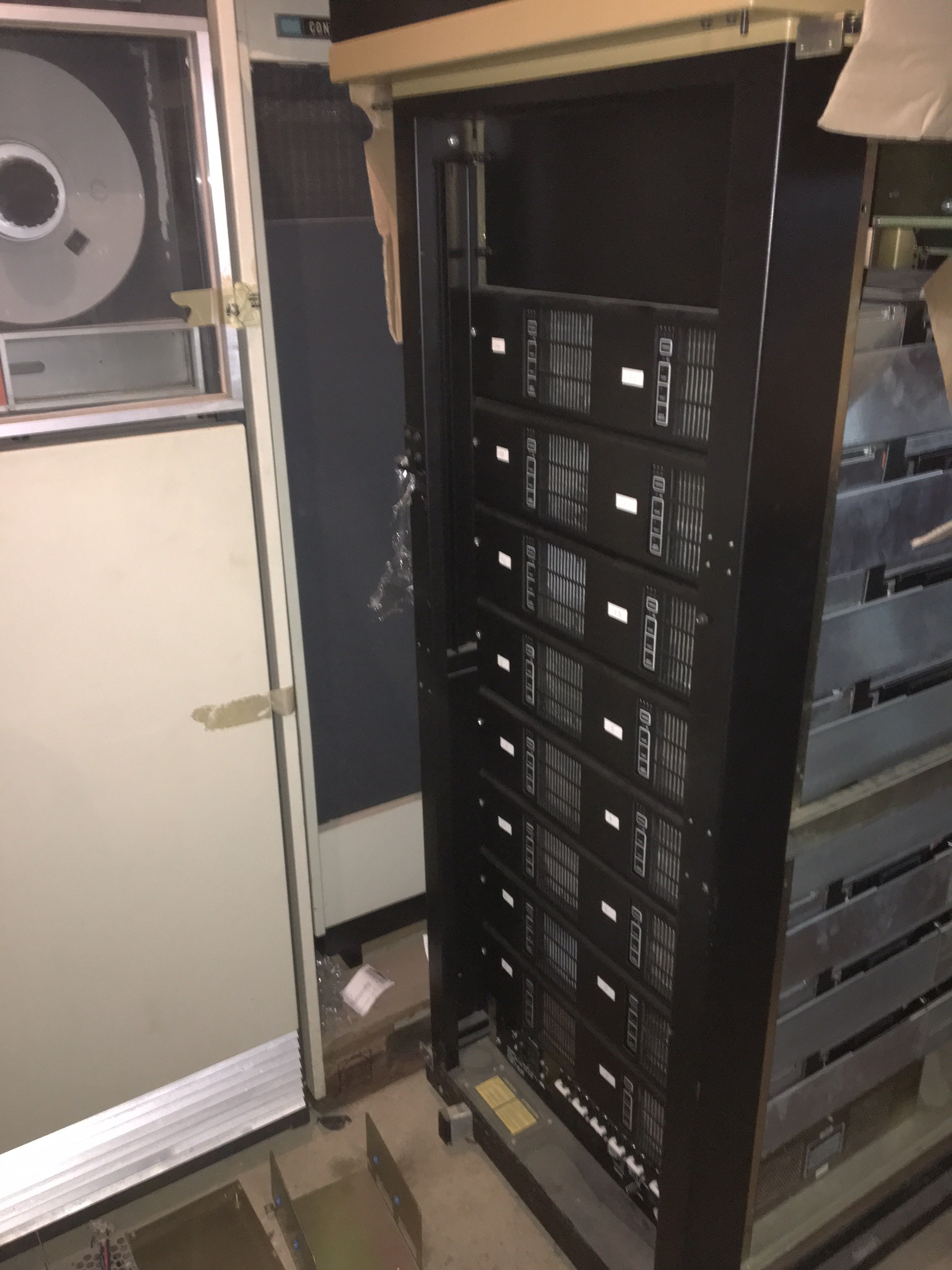
2017-07-29 - Arrival of the C220
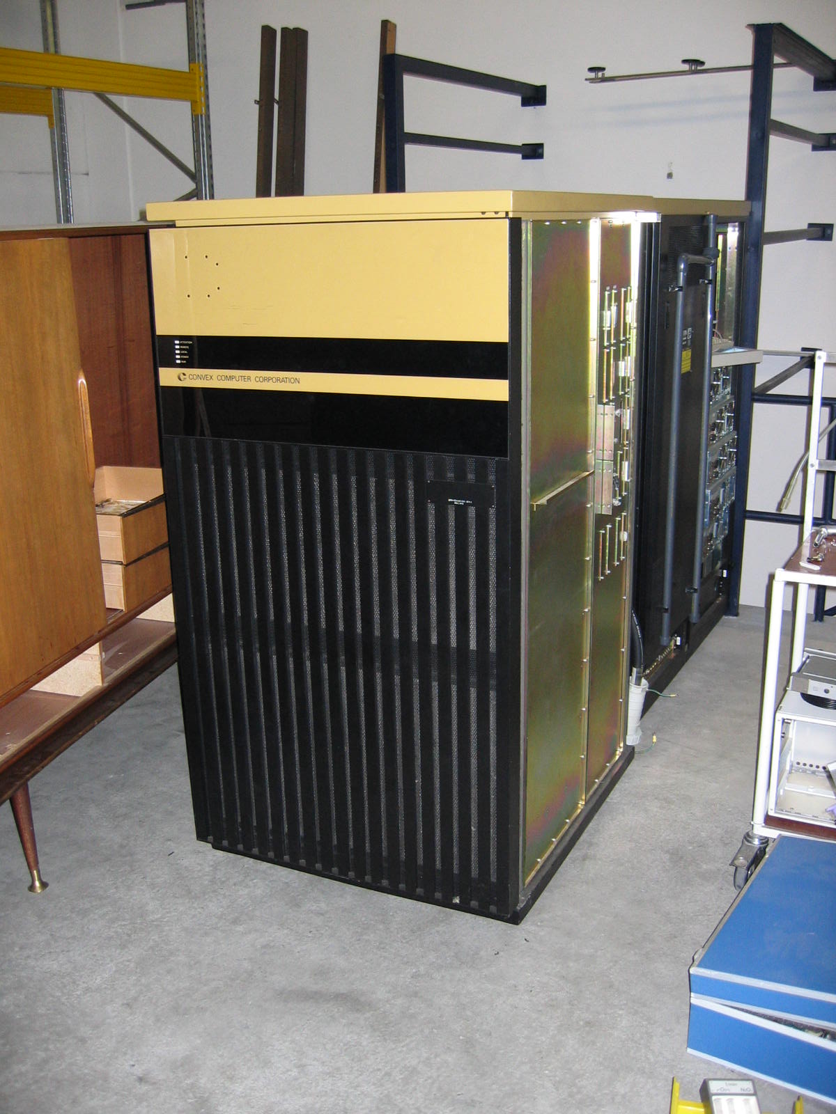
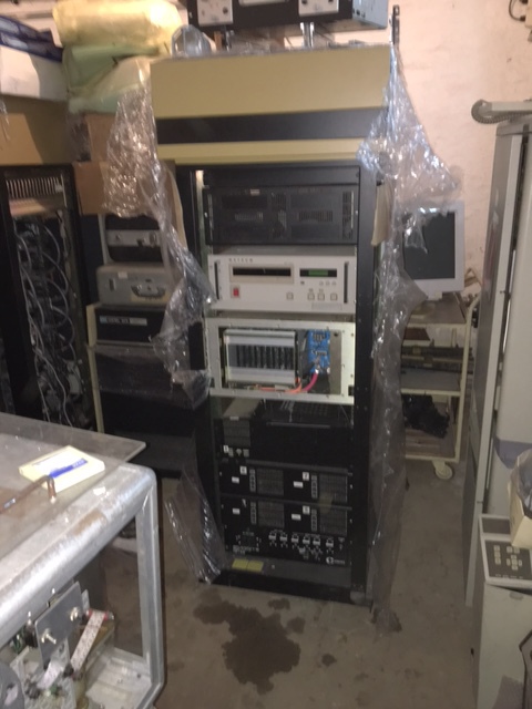
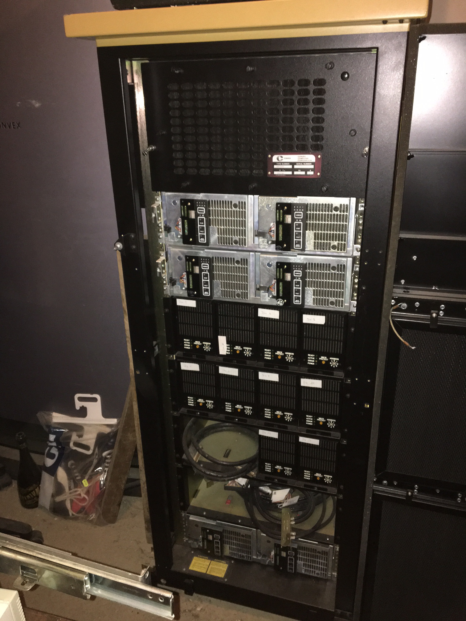
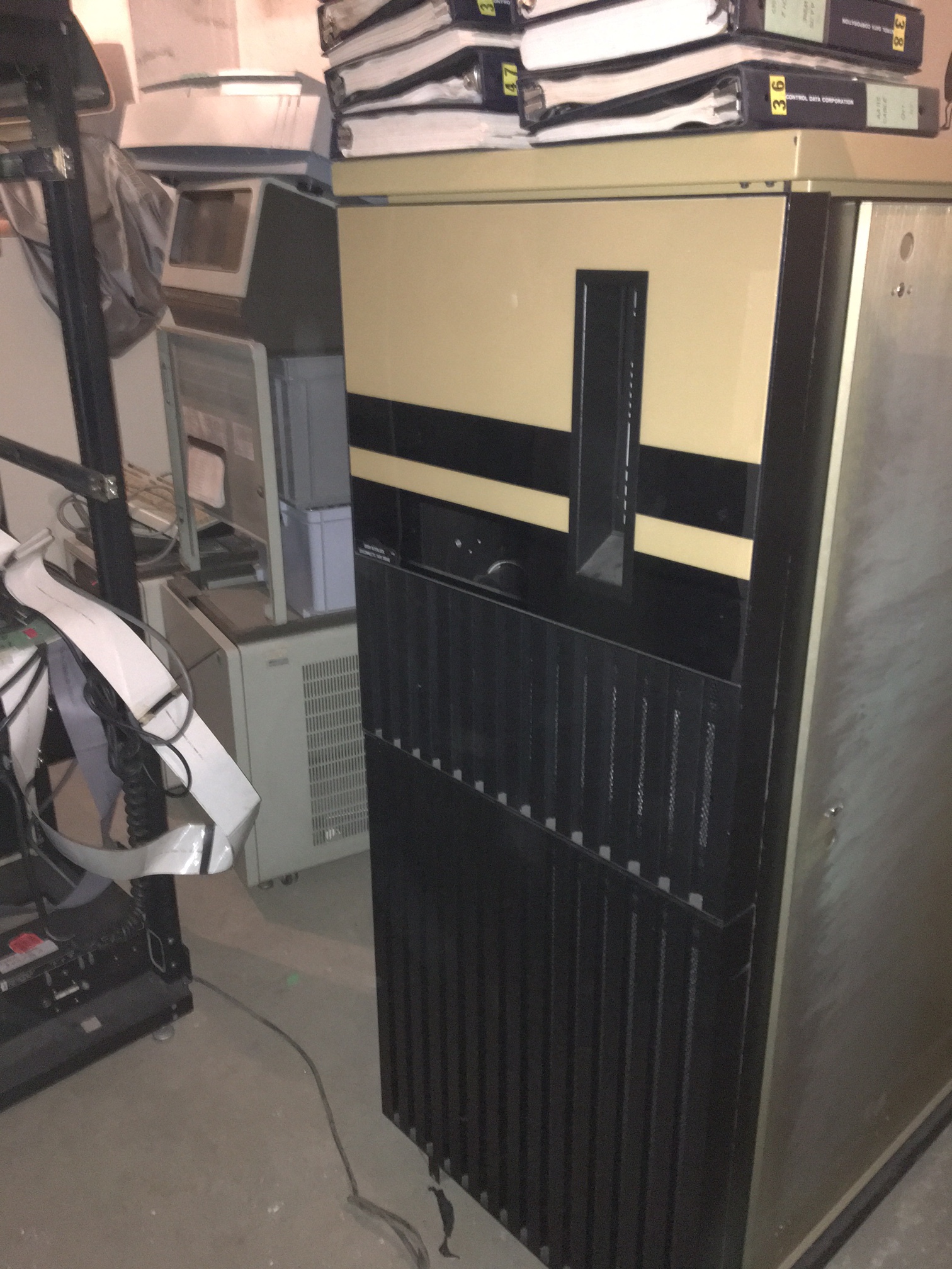
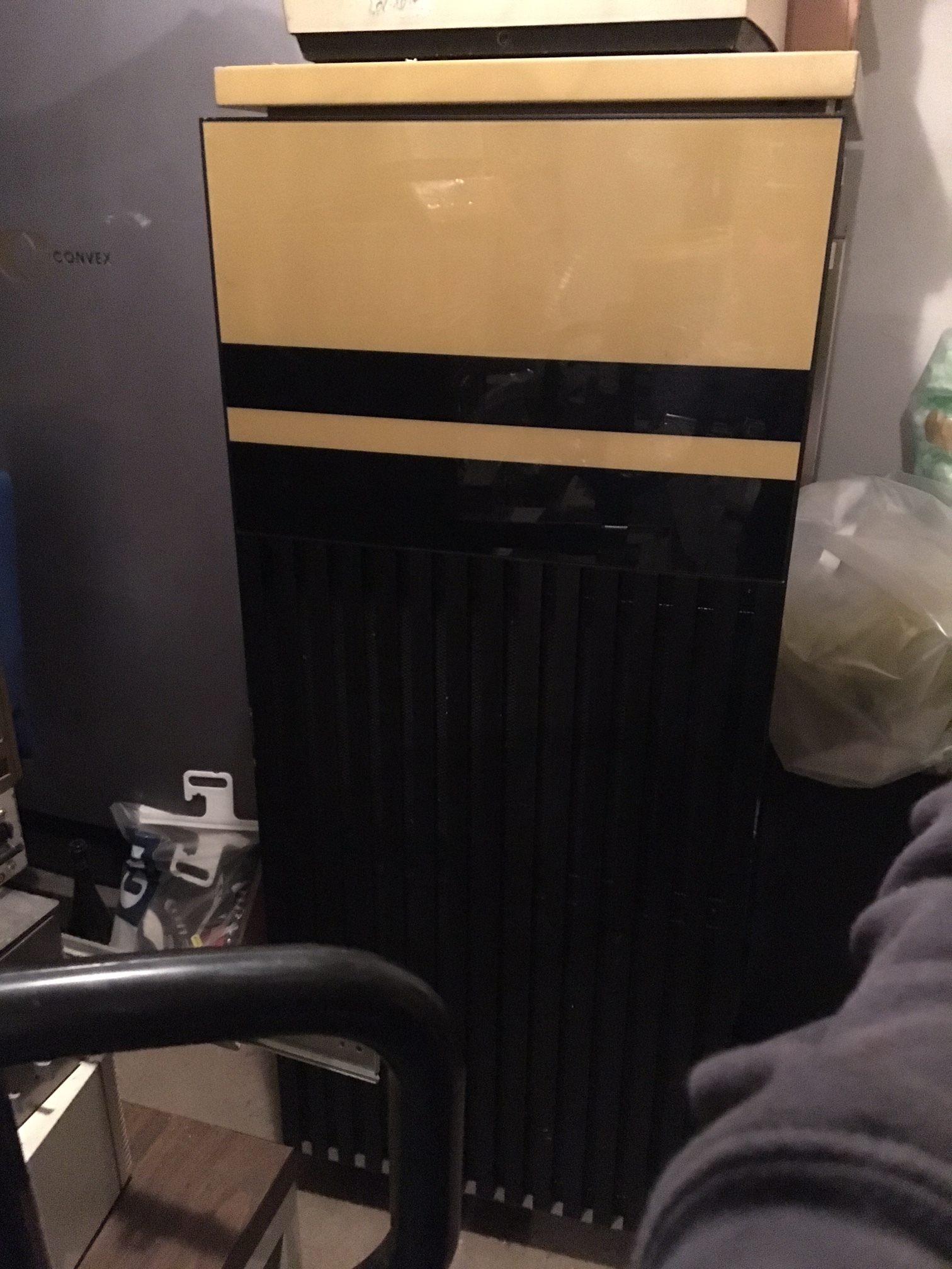
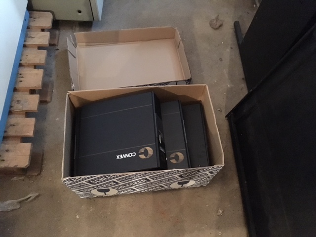
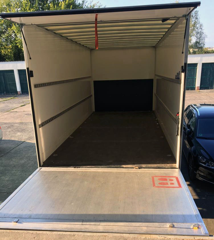
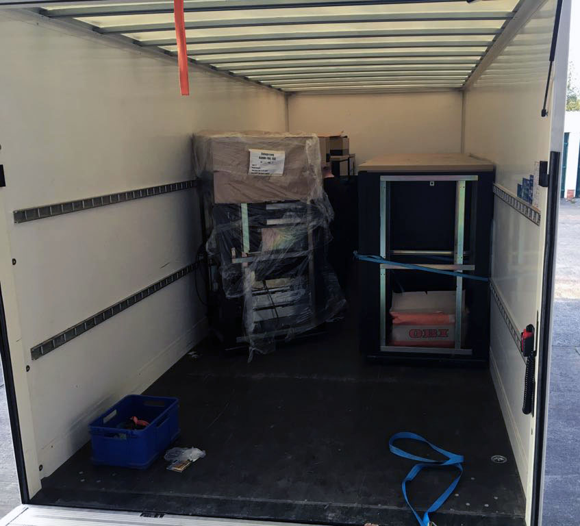
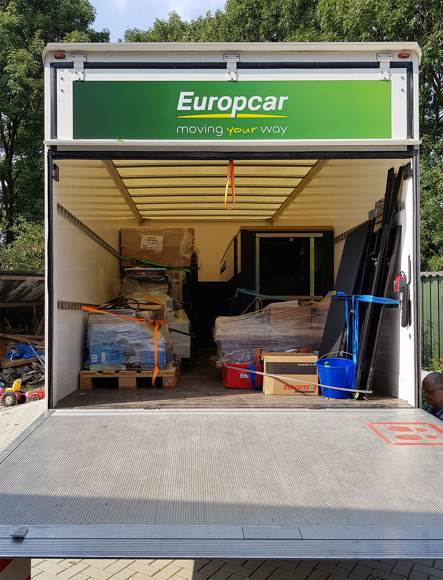
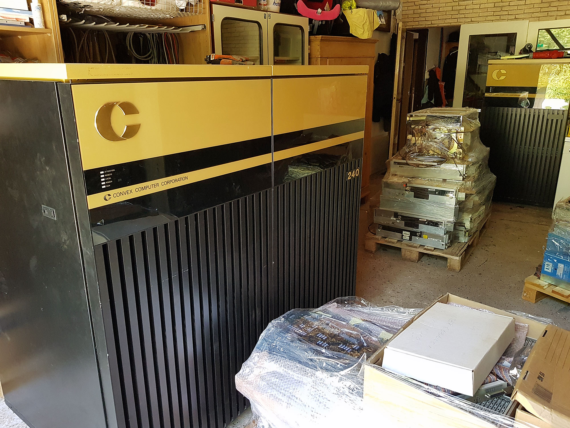
About a week ago, the Convex C220 arrived, this is the first part of the Convex C2 Shipment (the Convex C240 will follow three weeks from now). This first shipment consisted of the C220 cpu cabinet, a couple of empty cabinets, some spare parts, some software tapes, and a lot of documentation.
About a week ago, the Convex C220 arrived, this is the first part of the Convex C2 Shipment (the Convex C240 will follow three weeks from now). This first shipment consisted of the C220 CPU cabinet, a couple of empty I/O cabinets, some spare parts, some software tapes, and a lot of documentation. The second shipment will consist of the C240 CPU cabinet, more I/O cabinets, I/O devices, more spares, tapes and documentation.
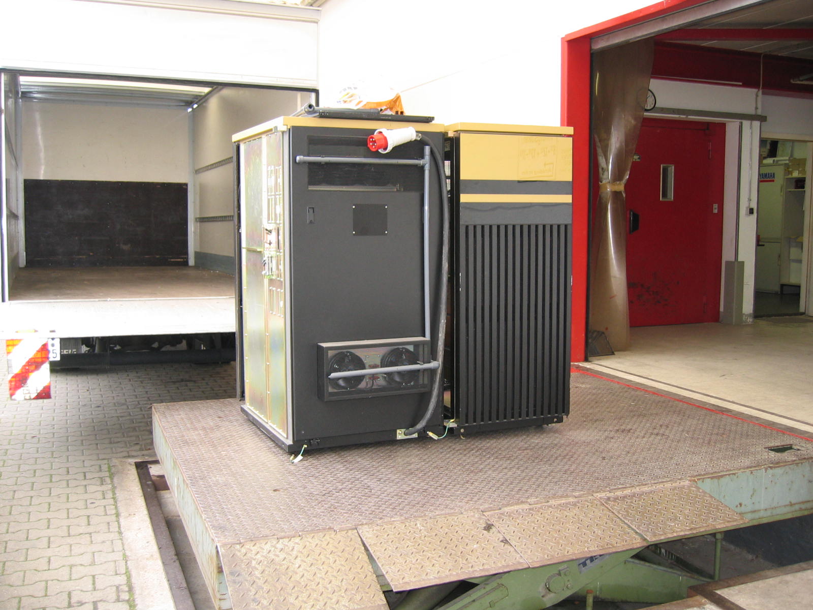
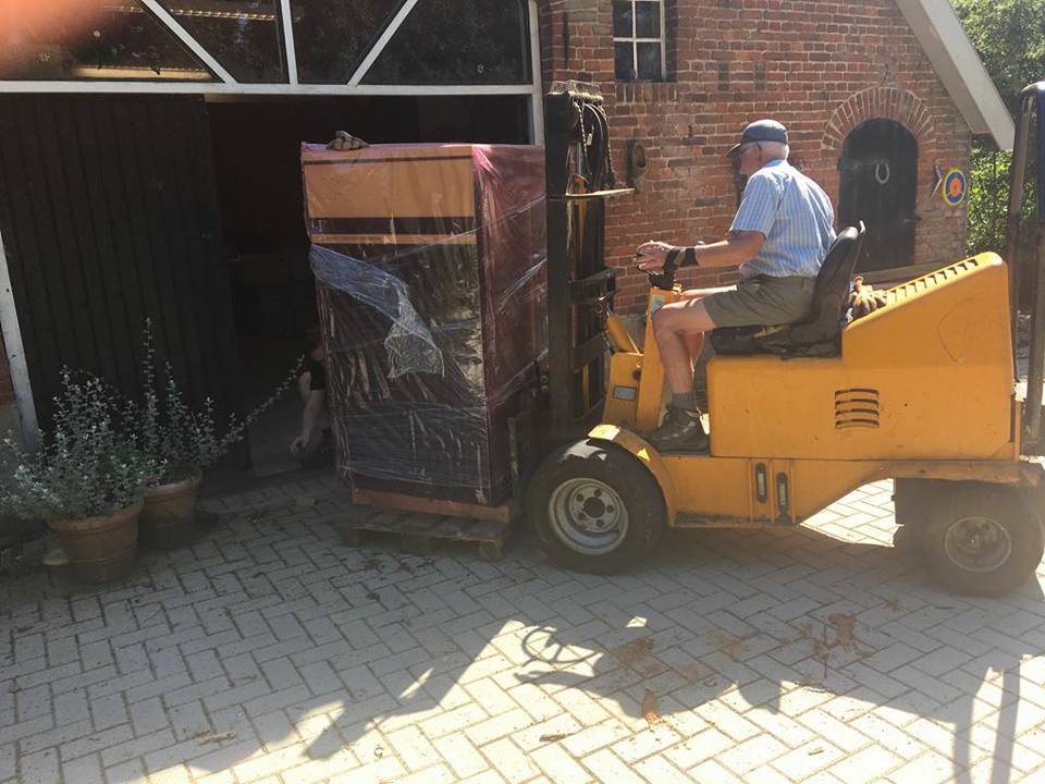
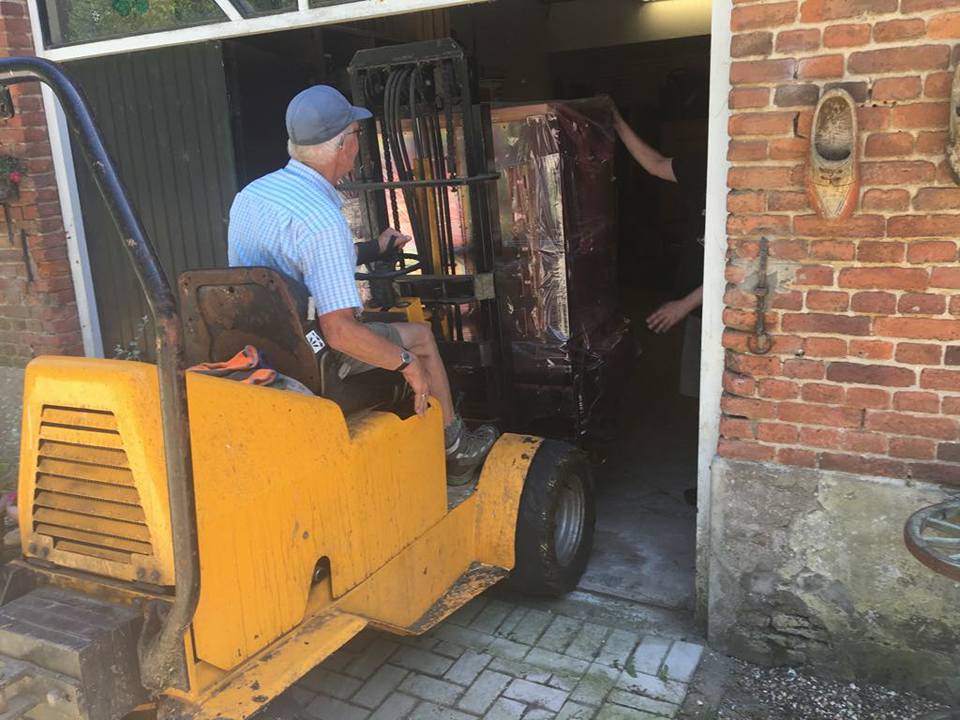
As you can see, getting the C220 CPU cabinet inside involved getting a helping hand from a local farmer, which was a first for the collection. The CPU itself is on wheels, but it was placed on a pallet. At first, I borrowed a manually operated pallet truck to move the CPU out of the van, but unfortunately the pallet truck was somewhat broken, and would not lift the CPU high enough to get over the threshold. After a phone call to Edwin, a farmer in our village we're friends with, he sent his father with a diesel pallet truck, which we used to lift the CPU from its pallet, and put it inside.
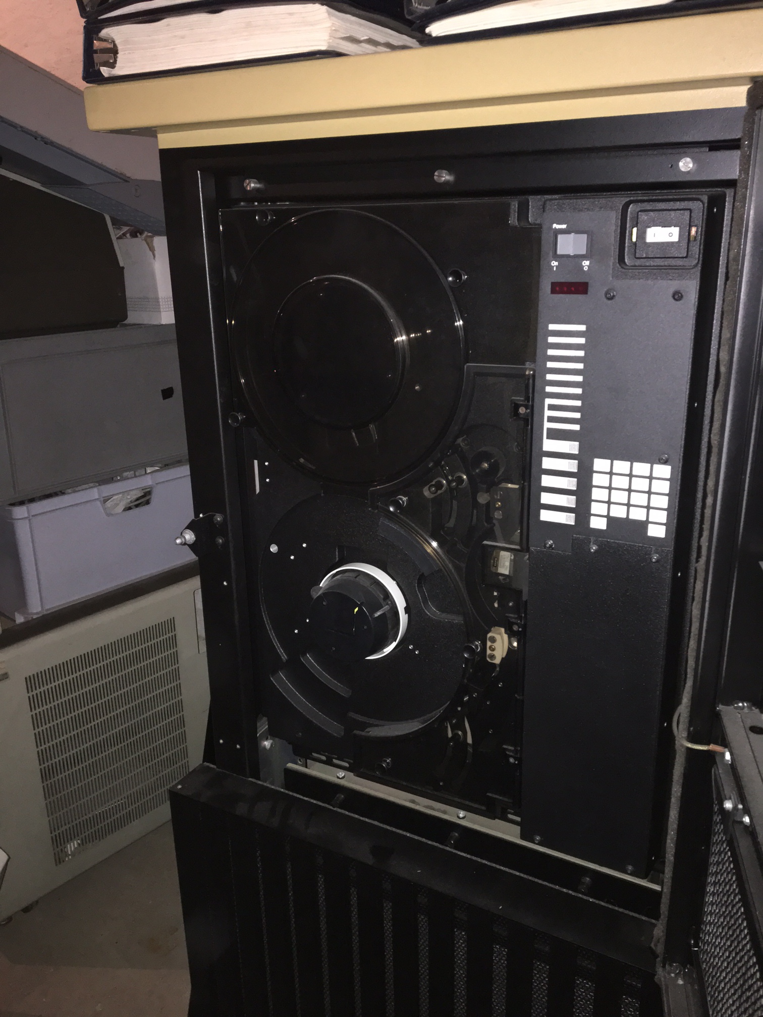
Acq C2 C220 1
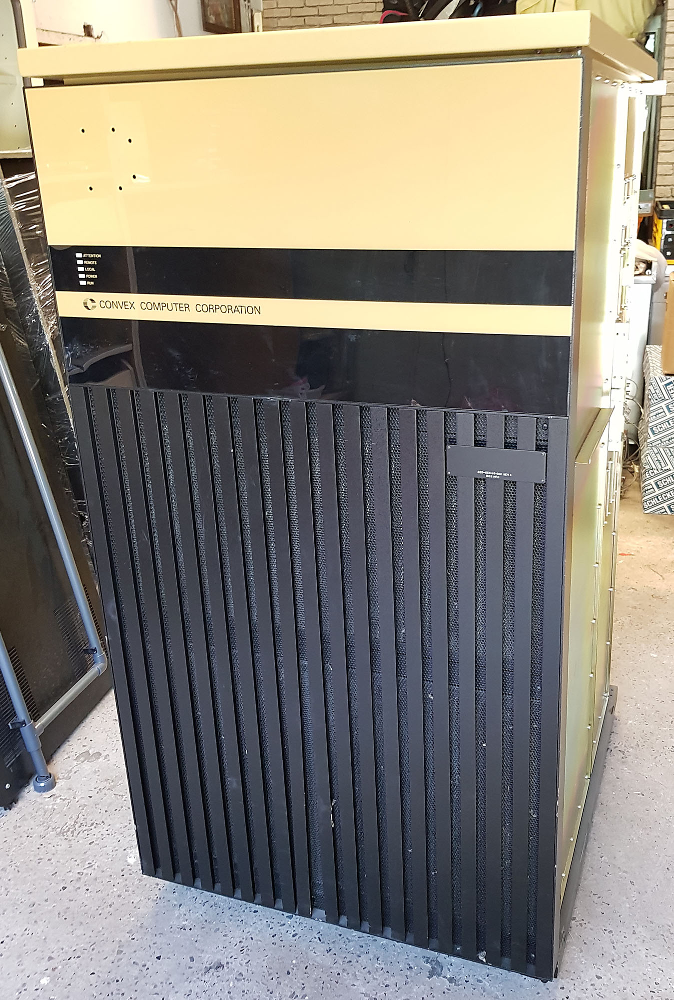
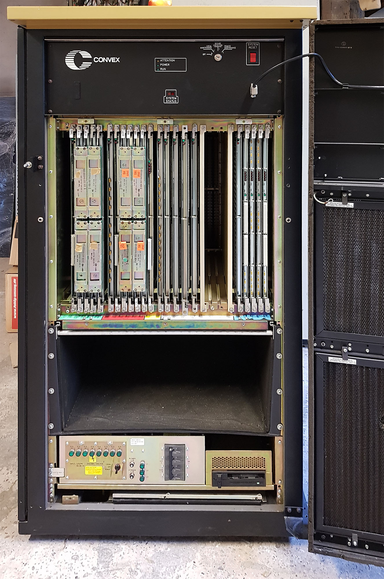
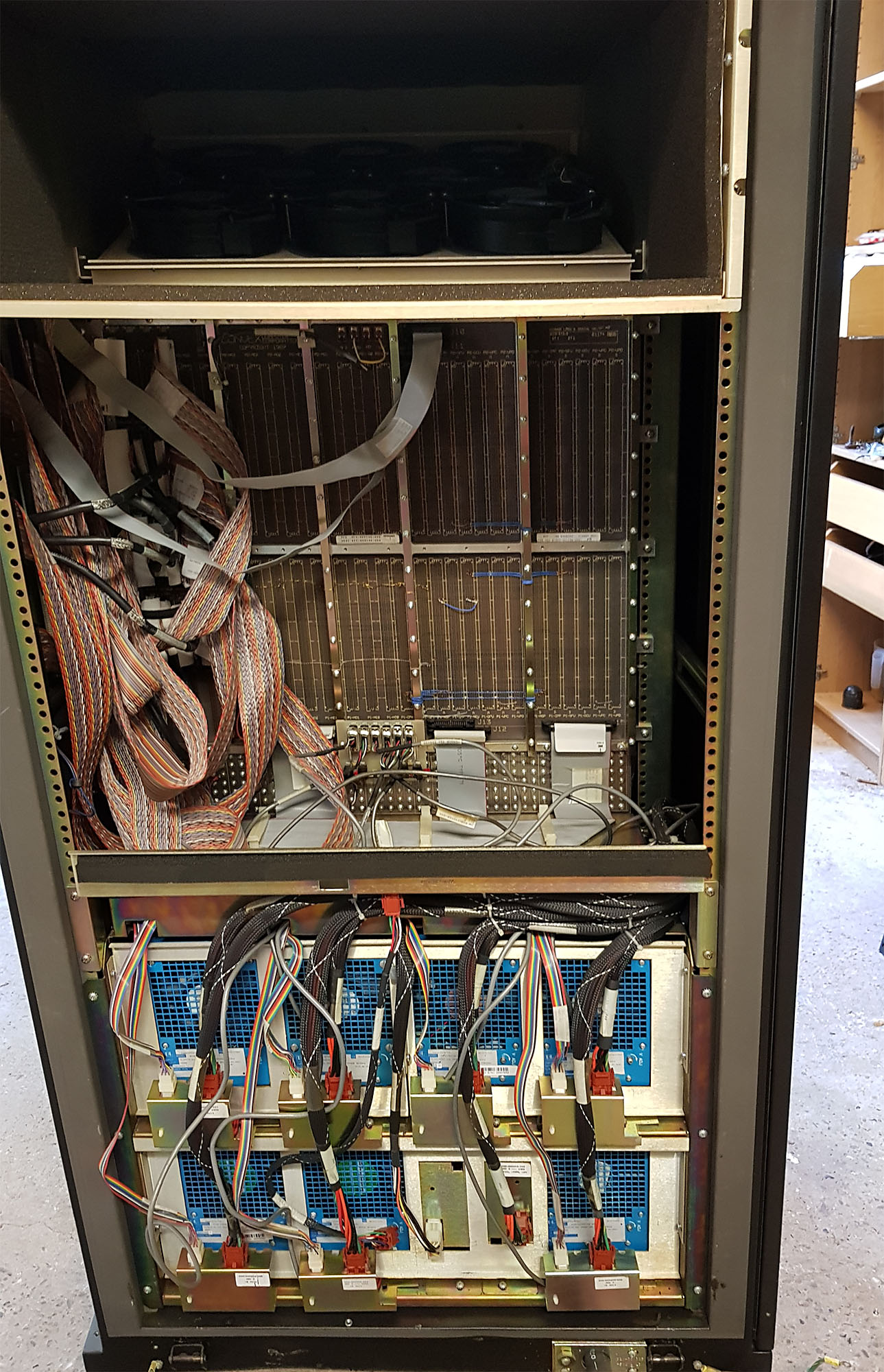
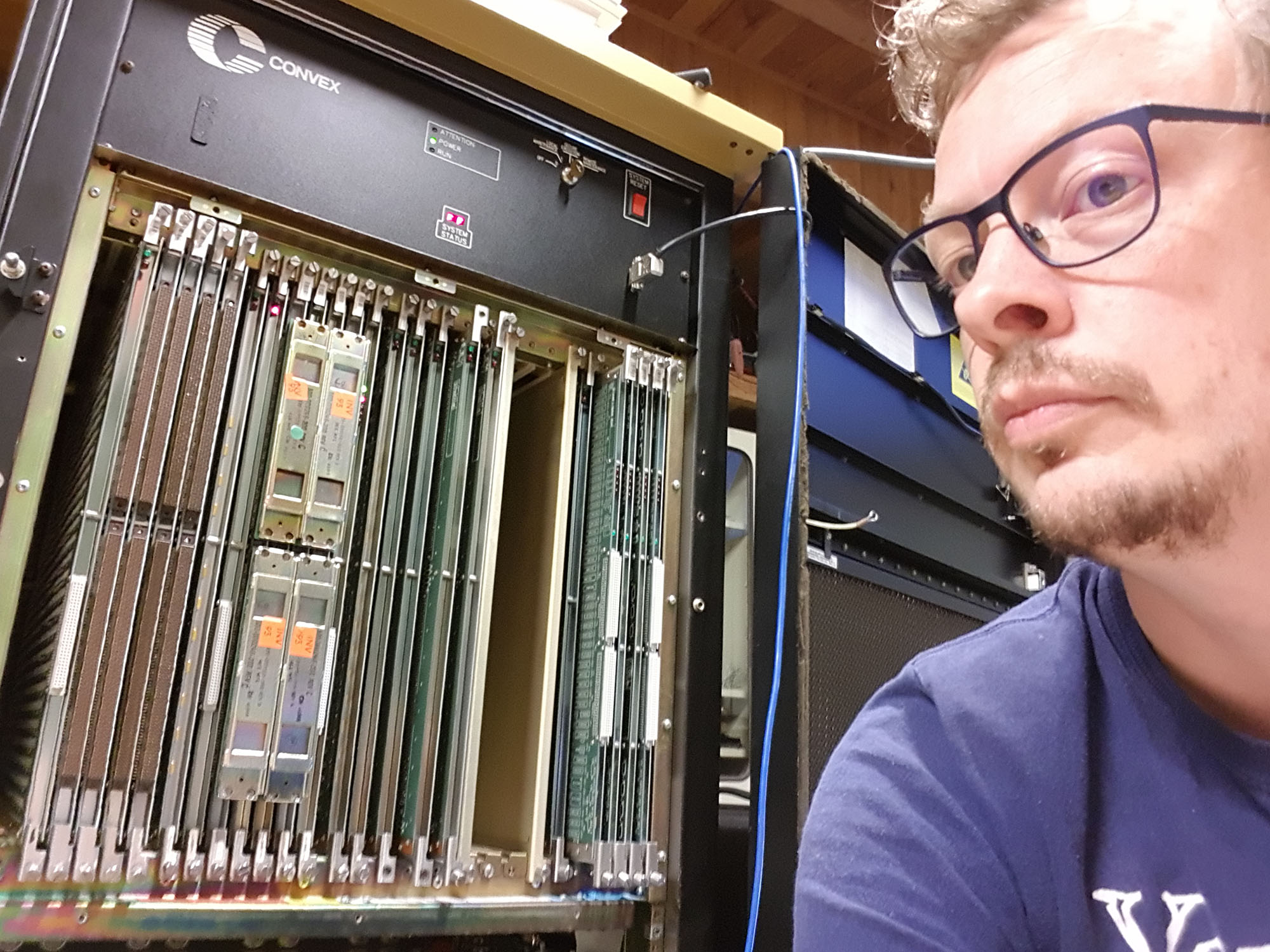

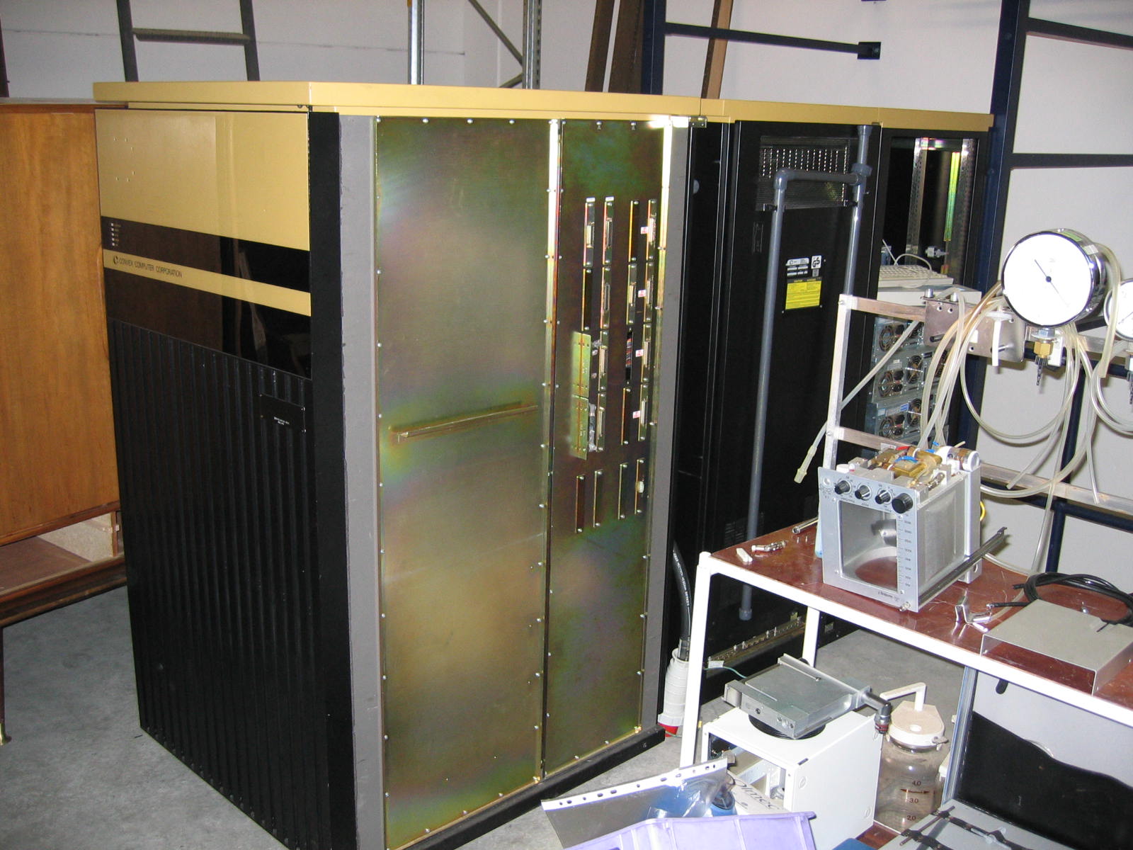
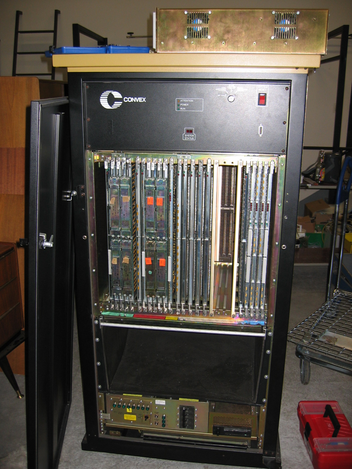
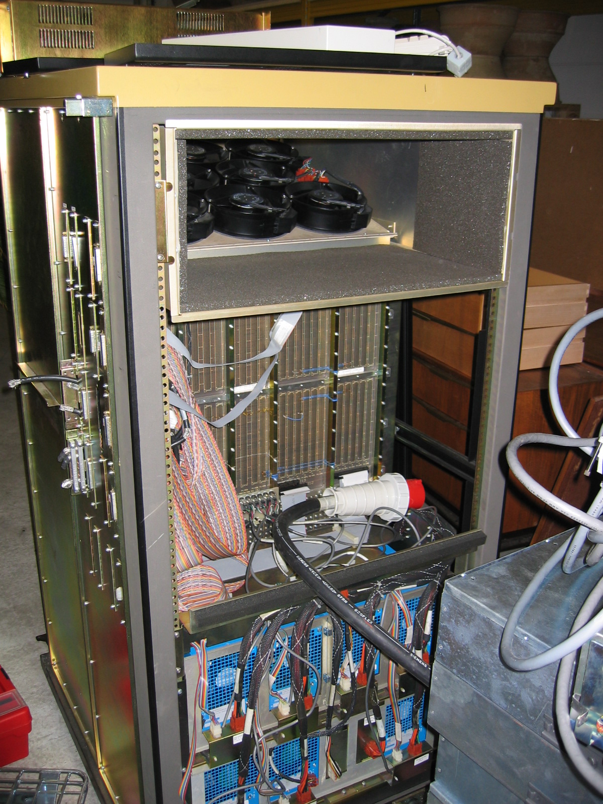
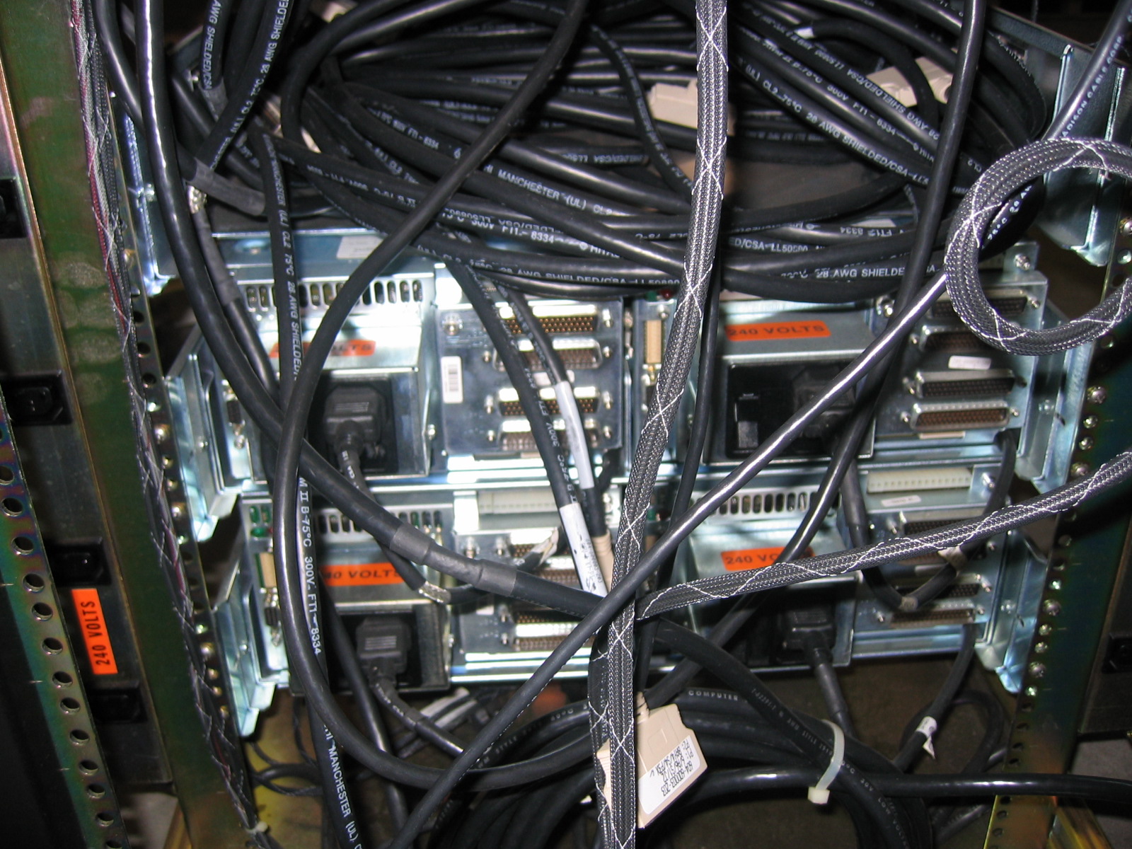
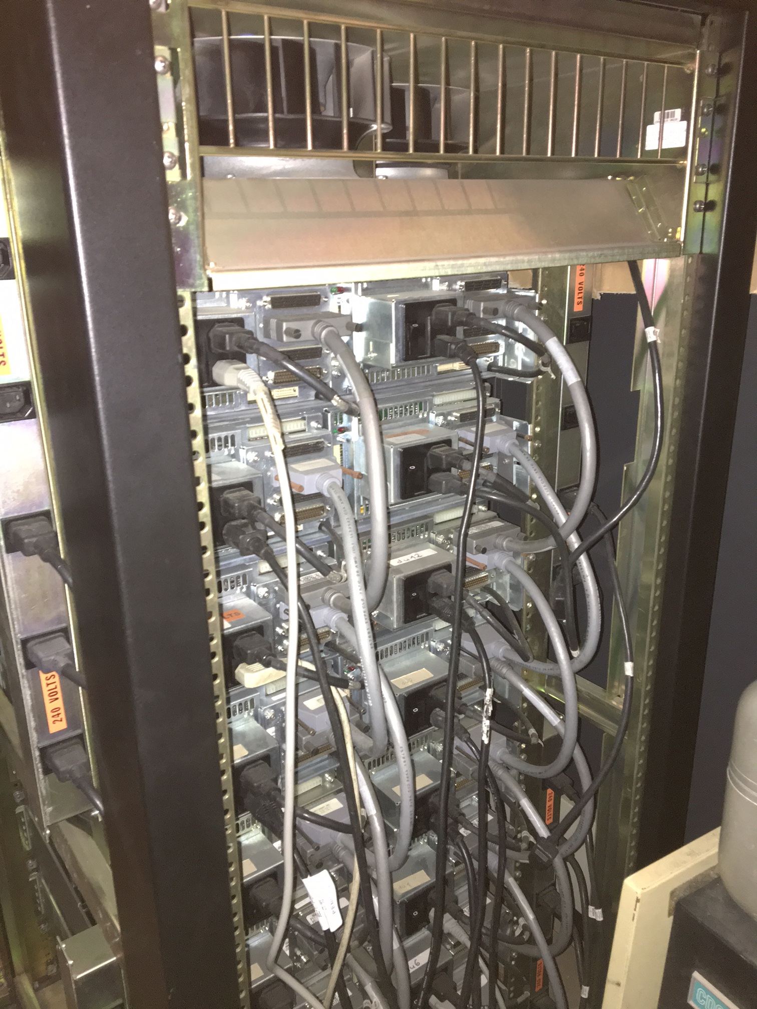
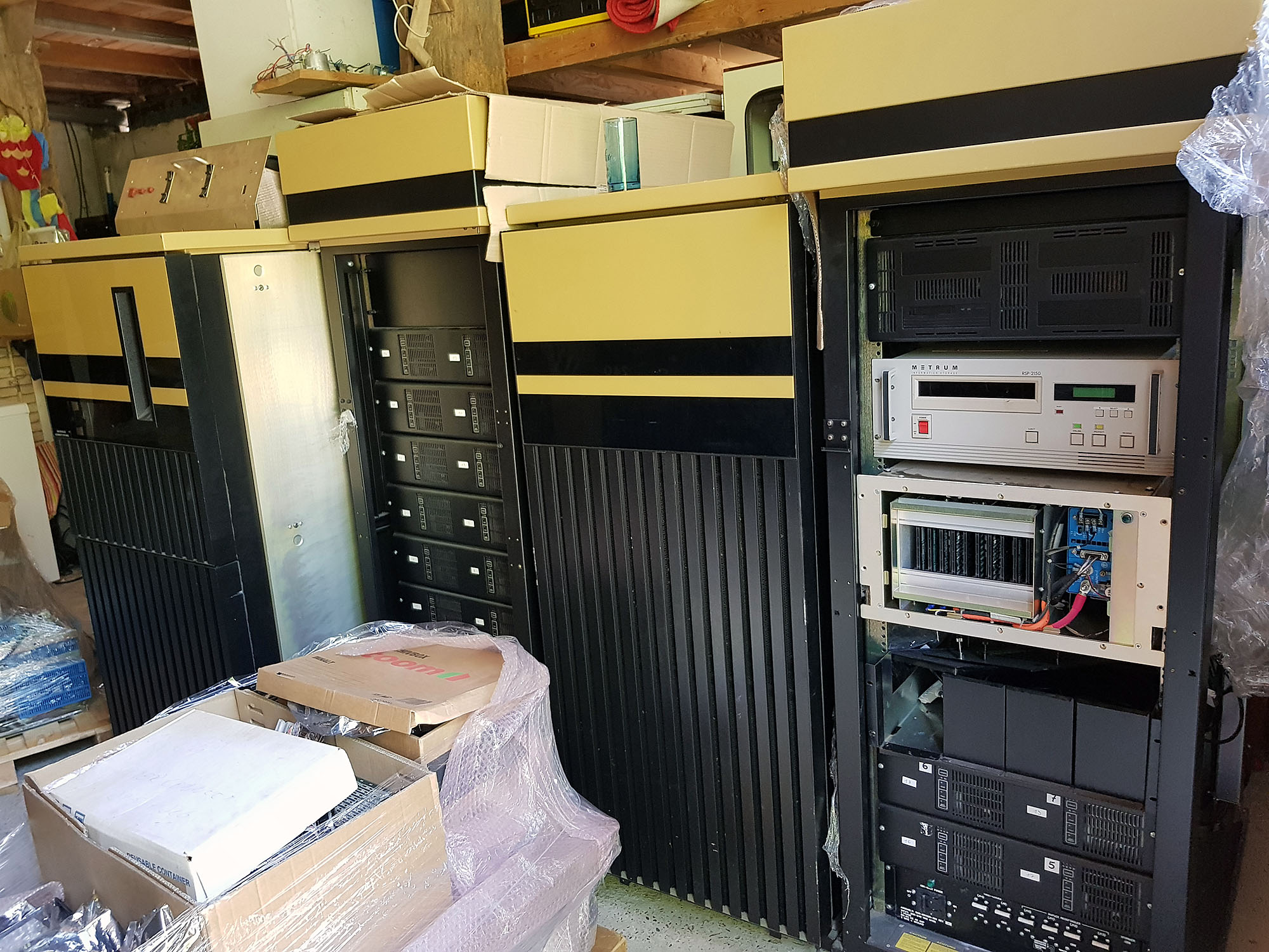
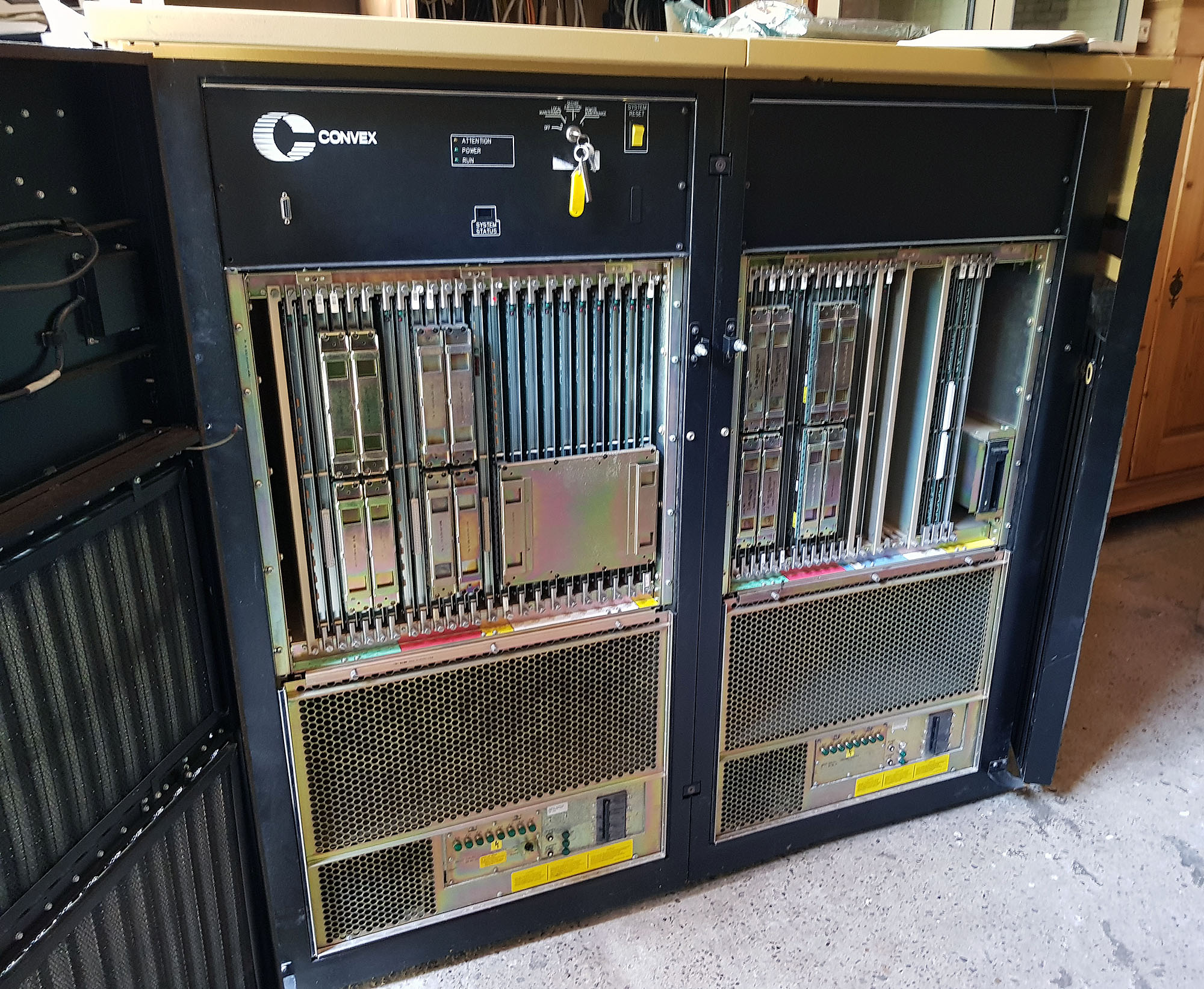
The C220's CPU cabinet is a bit wider than the standard 19" racks used for the I/O cabinets and for the Convex C1 XP's CPU. After opening the front door, a well-populated cardcage becomes visible. At the back of the CPU, below the backplane, you can see the 8 power supplies:
- 4 x 400A @ -4.5V
- 2 x 400A @ -2V
- 1 x 400A @ 5V
- 1 x small change @ -5/+12/-12V
Of course, what really gets the attention is the 1600 amperes delivered into minus 4.5 volts, and the 800 amperes delivered into minus 2 volts. Those familiar with exotic processor technology may correctly guess from this that this is an ECL machine. ECL (Emitter Coupled Logic) uses negative signal levels. Rather than use the transistors as on/off switches, the transistors in ECL logic are always conducting energy. By avoiding the cutoff and saturation regions of the transistors behavior, higher switching speeds can be achieved. This comes at the expense of power consumption and component density.
The -4.5 volts is the power supply for the ECL logic. In addition to that, every ECL output signal needs termination. Traditionally, this was done through a resistor network, one resistor to the negative power supply, and one resistor to ground. In this machine, however, a second power rail (-2 V) is used for termination through a single resistor, which reduces the power draw a little bit.
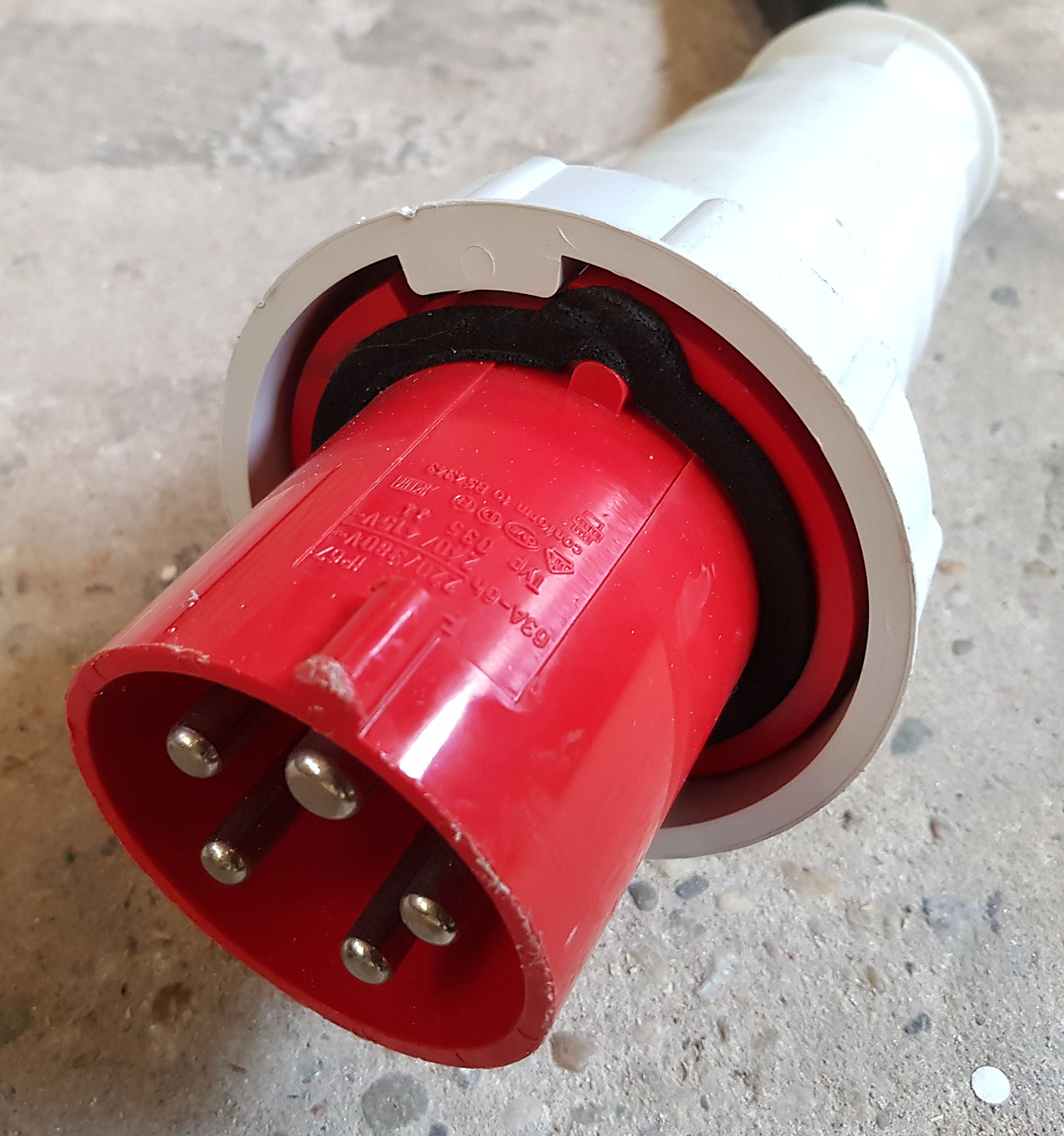
The power cable for this system is fitted with a 63 ampere 3 phase plug; I needed to use two adapters to hook it up to a 16 ampere 3-phase circuit.
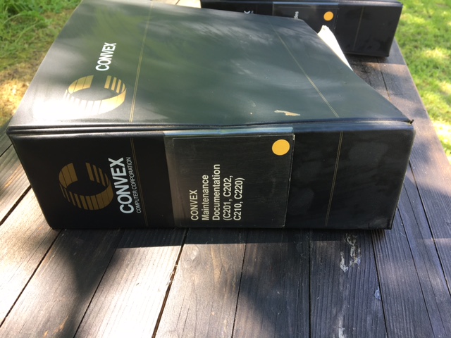
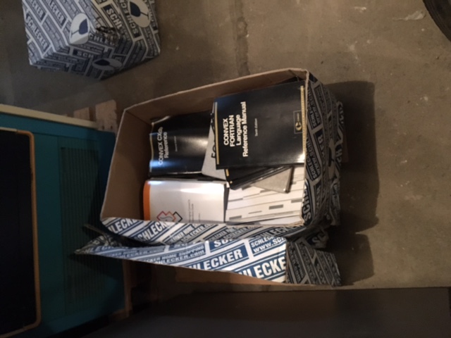
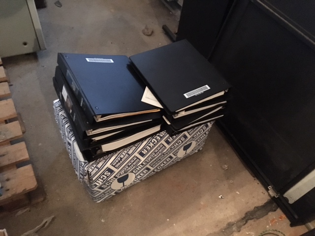
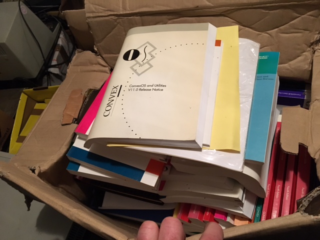
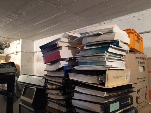
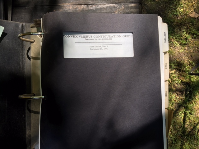
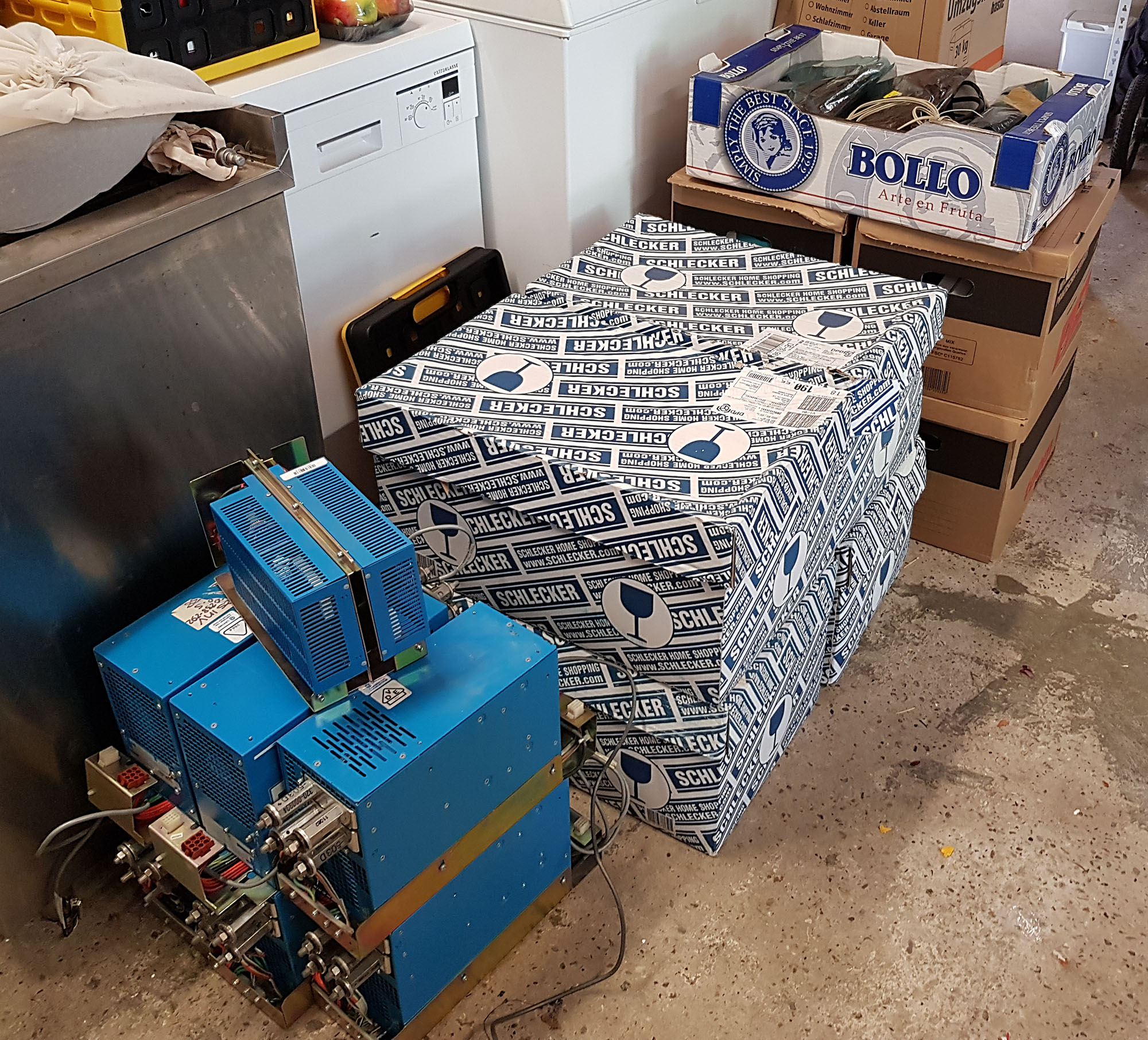
Also visible in one of the photos are spare power supplies, and boxes of spare parts, installation tapes, and documentation. So far, I have scanned some of the documentation (in total, there are some 300 publications in there), and made it available in the Convex Documentation article.
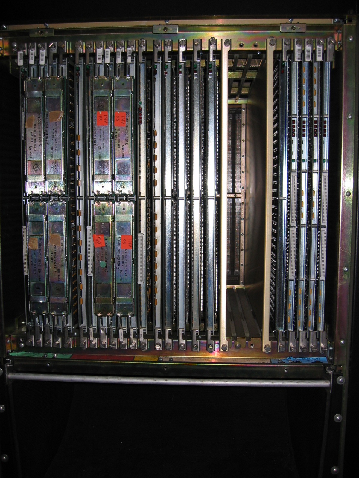
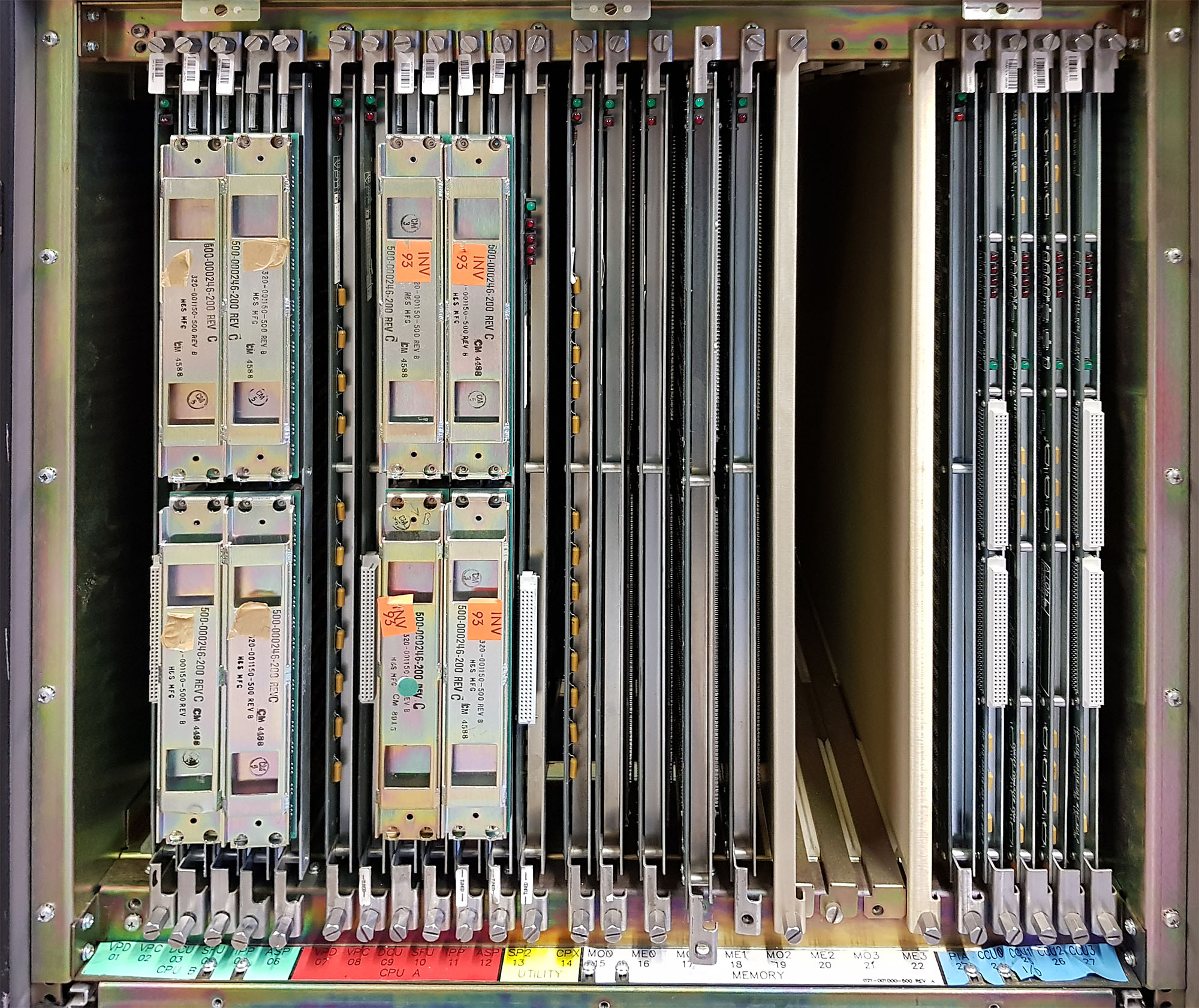
The 27-slot cardcage holds the following components:
Two CPU's
On the left side are the two CPU's, each consisting of 6 cards.
Acq C2 C220 Cpu 2
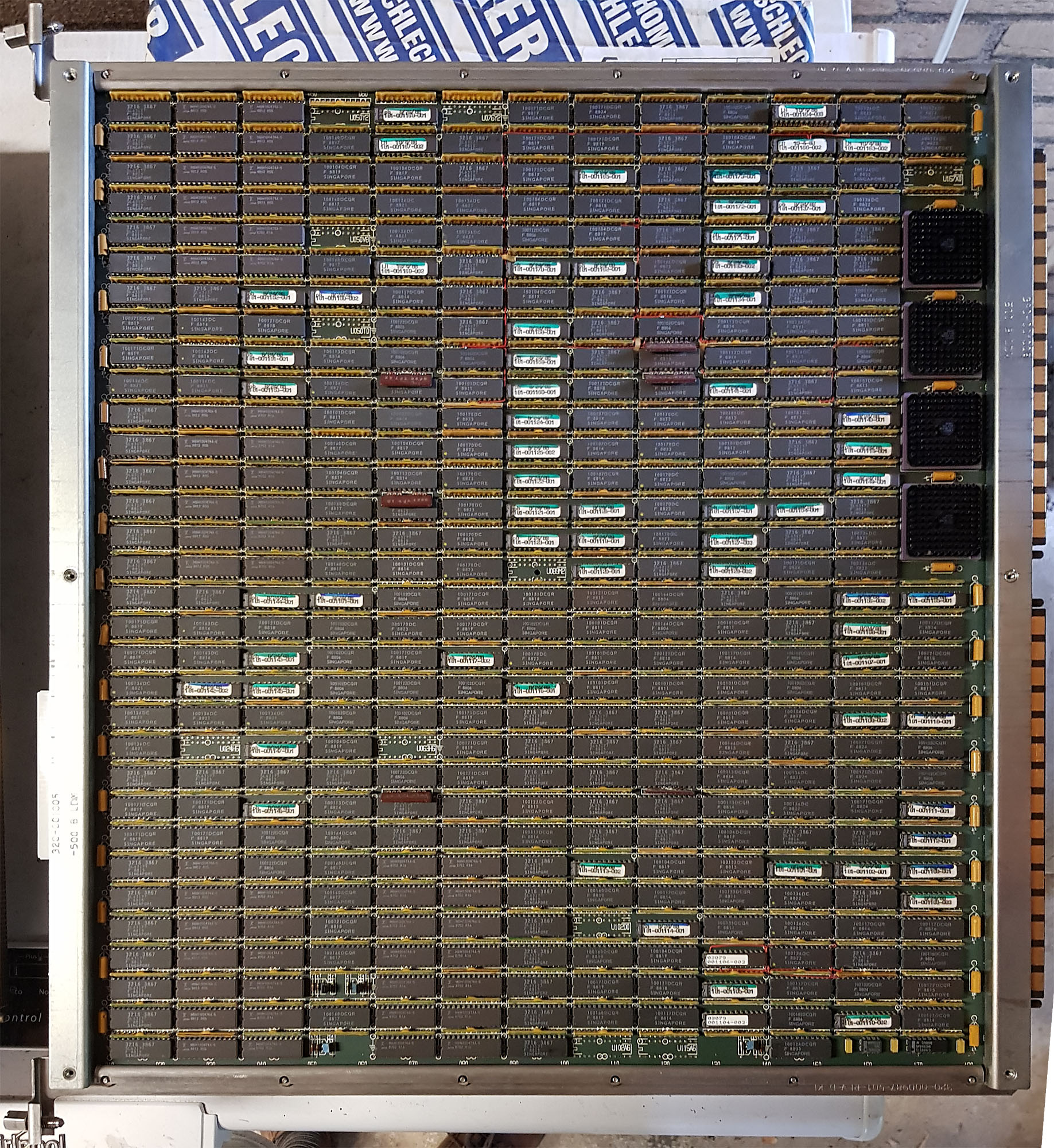
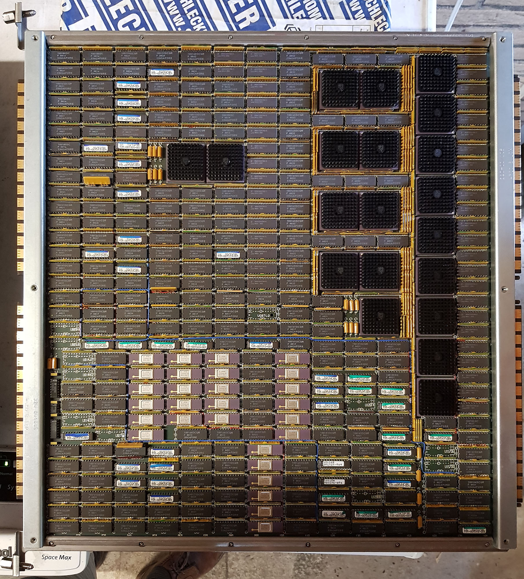
These cards are:
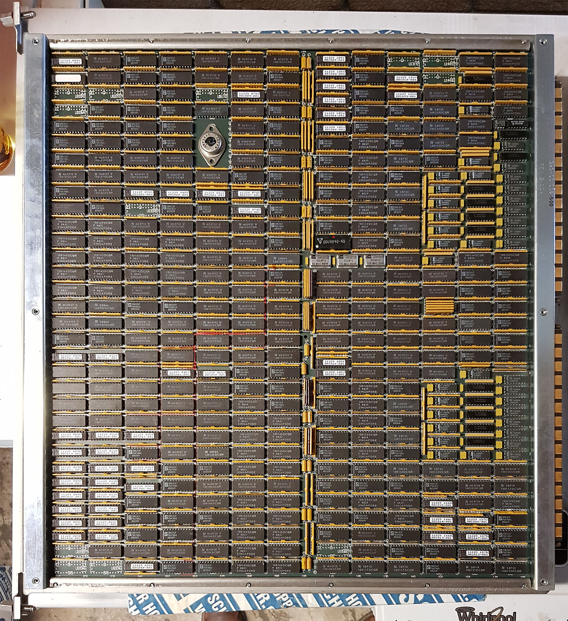
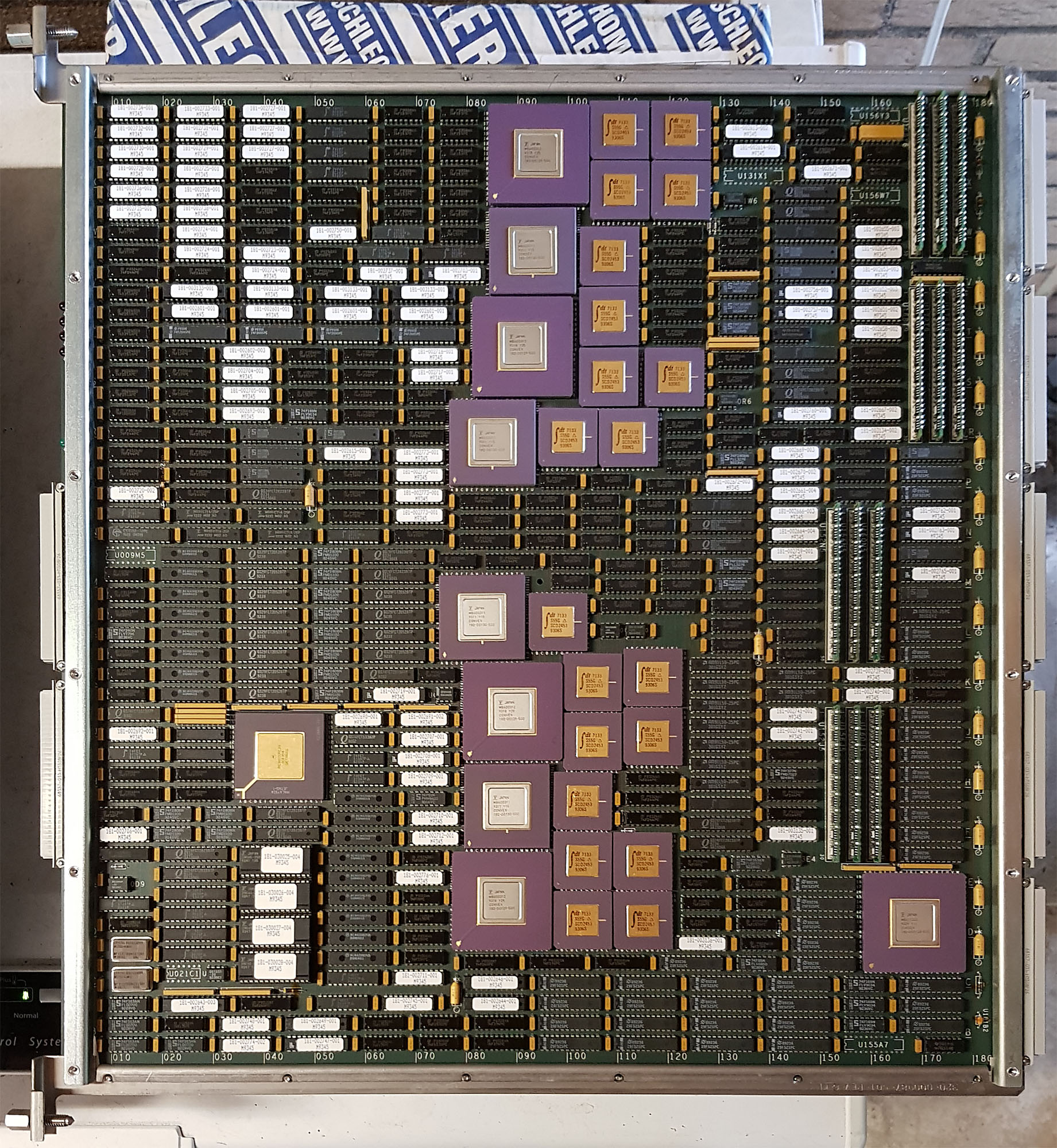
- VPD - Vector Processor Data
- VPC - Vector Processor Control
- DCU - Data Cache Unit
- SFU - Scalar Function Unit
- IPP - Instruction Pre-Processor
- ASP - Address/Scalar Processor
Vector instructions are executed on the VPD and VPC cards, memory accesses for these instructions bypass the cache. Scalar instructions are executed by the SFU, accessing memory through the data cache on the DCU. Instructions are dispatched by the IPP, which determines whether the instruction needs to be executed by the vector processor or the scalar processor, takes care of the instruction pointer, and handles conditional execution (so the actual processor only sees those instructions that need to be executed). Finally, all memory accesses, for both scalar and vector data, and for instruction fetches, go through the ASP to get to the main memory.
The DCU and SFU, and the IPP and ASP are connected on the front of the machine as well, using two of the 300-pin connectors jumpered together, and mounted on a sturdy metal bracket for strain relief.
Support and Memory
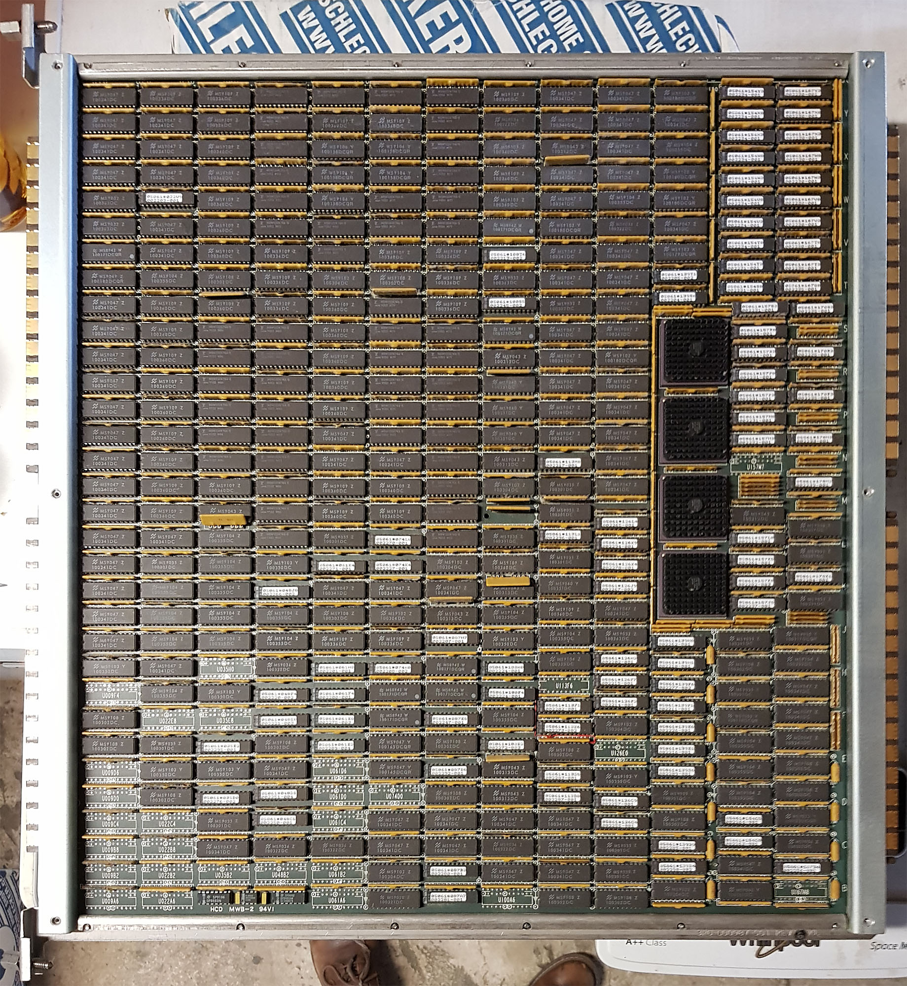
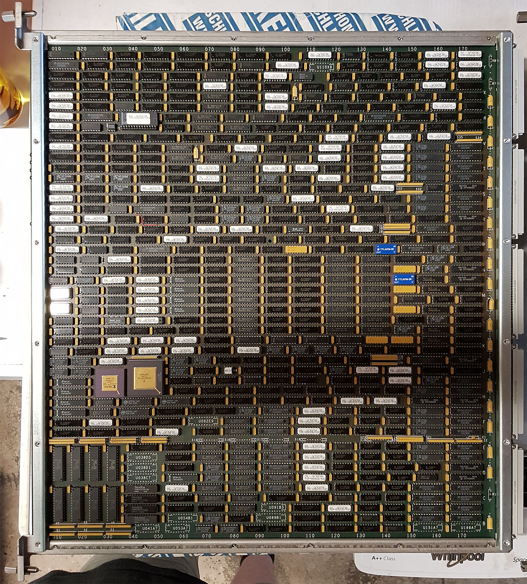
In the middle part are two support boards:
Acq C2 C220 Aux 3
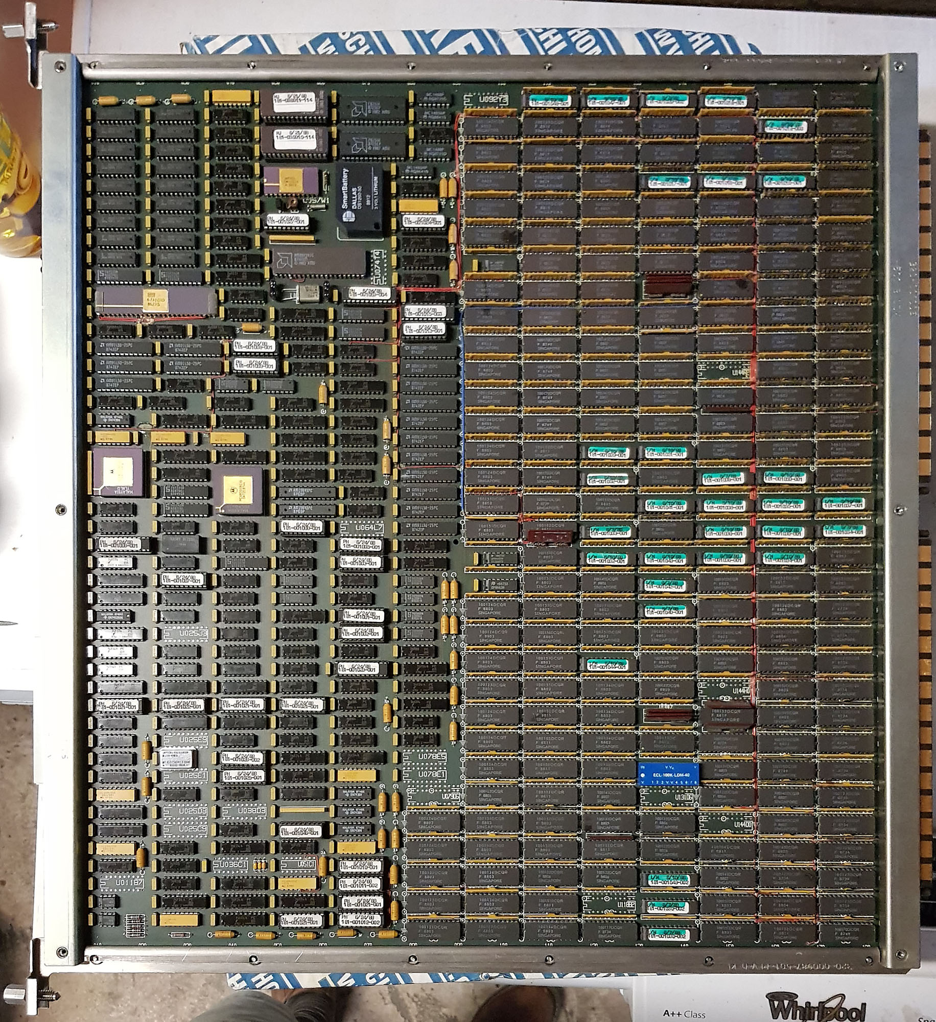
- SP2 - Support Processor (for 2 CPUs)
- CPX - CPU Utilities Board
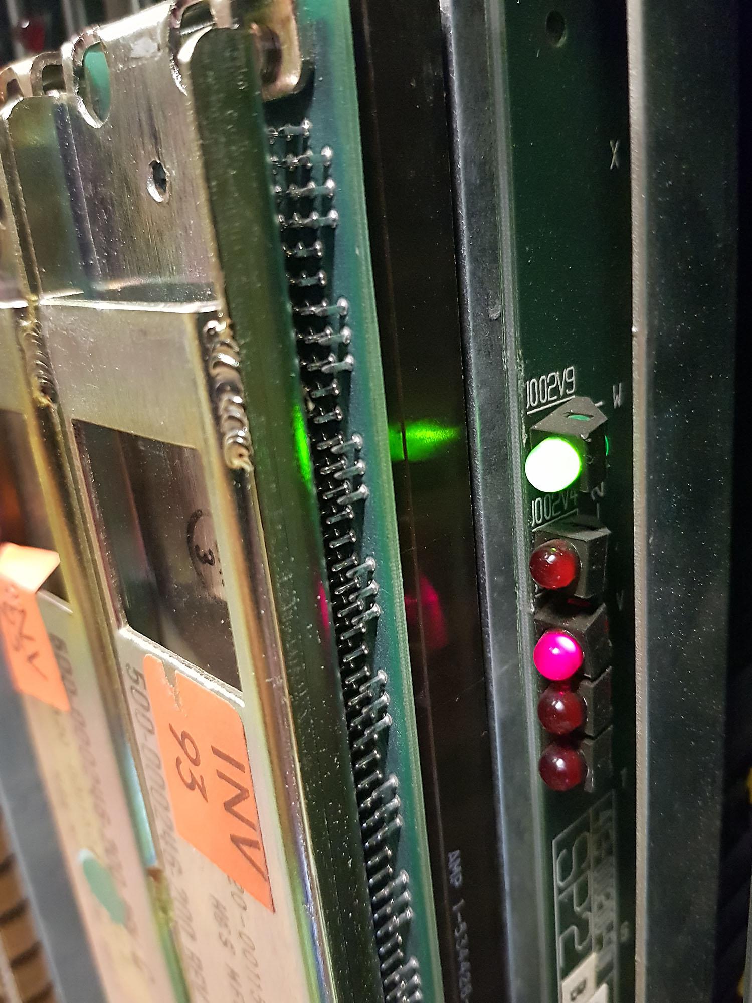
The SP2 is a computer in itself, based around a Motorola 68000 CPU. It is used for diagnostics and booting, and during operation, the SP2 monitors the operation of the entire machine. The SP2 is connected to the SCM (System Control Module), mounted below the card-cage. The SCM is a very simple computer, built around a 6805 micro controller. It is powered on as soon as power is supplied to the system and the main breaker is on, through a small linear power supply. The SCM monitors the environment, power supplies and fans, preventing power from being delivered to the main cardcage if operation is unsafe, and shutting the system down quickly when there's a problem. At power-on time, the SCM also checks to see whether the correct cards are installed; if the wrong type of card is installed in any slot, the SCM will prevent powering on the machine.
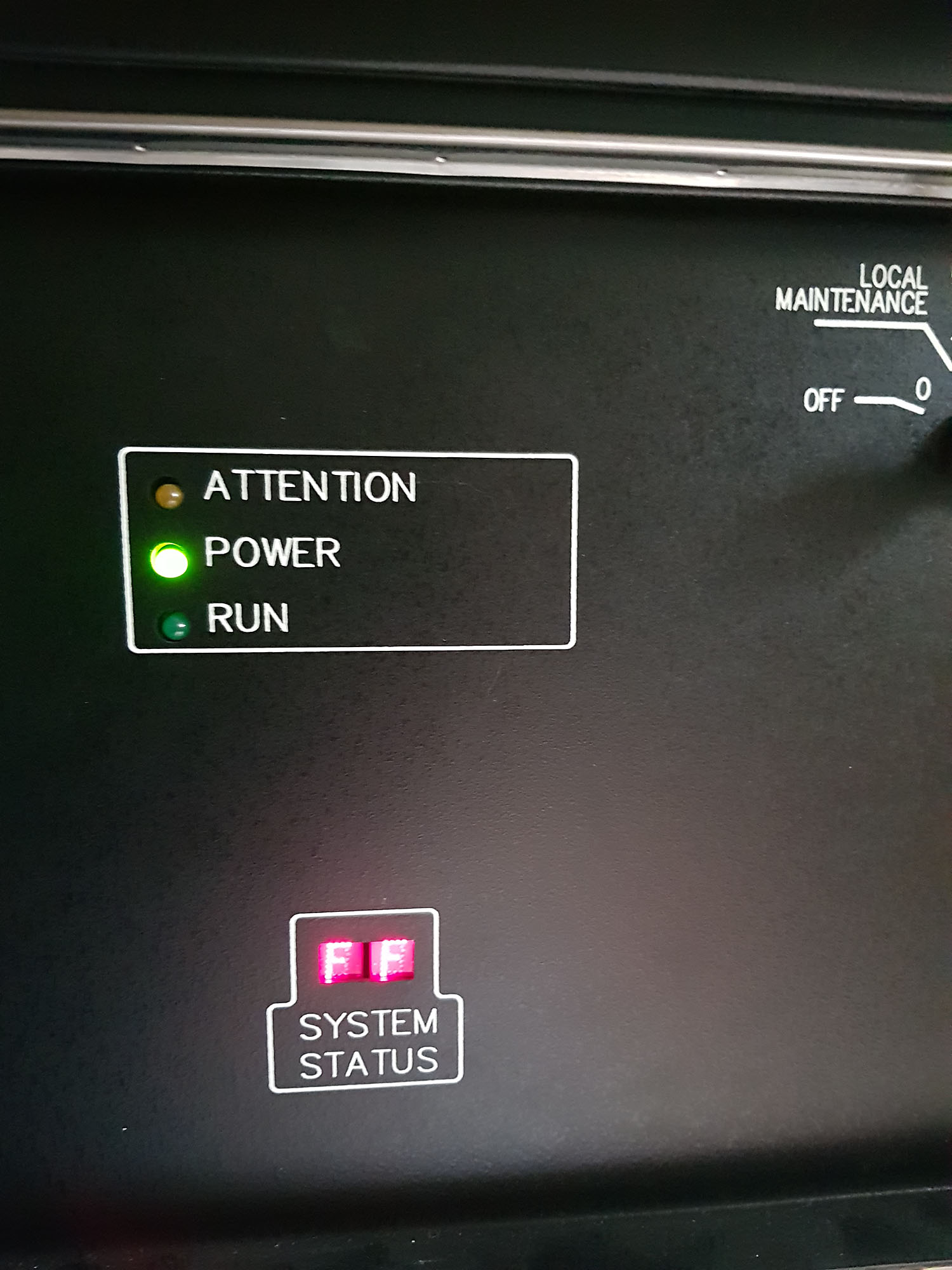
The SCM's status can be seen on a small 2-digit hexadecimal display on the front of the machine. FF indicates no problem, other codes indicate a problem or warning. These codes are listed on the inside of the front door.
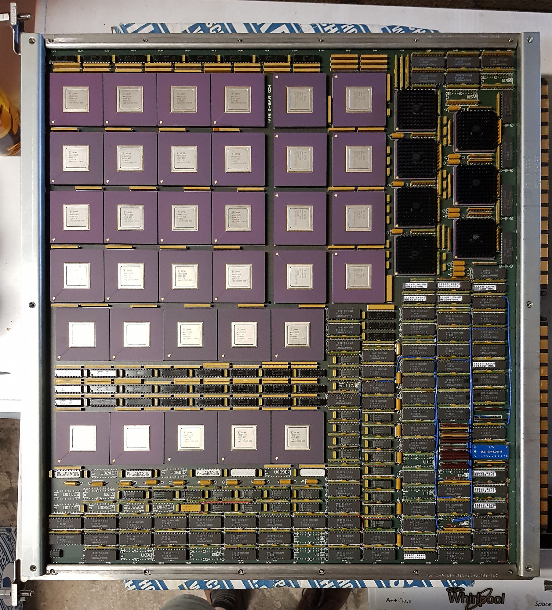
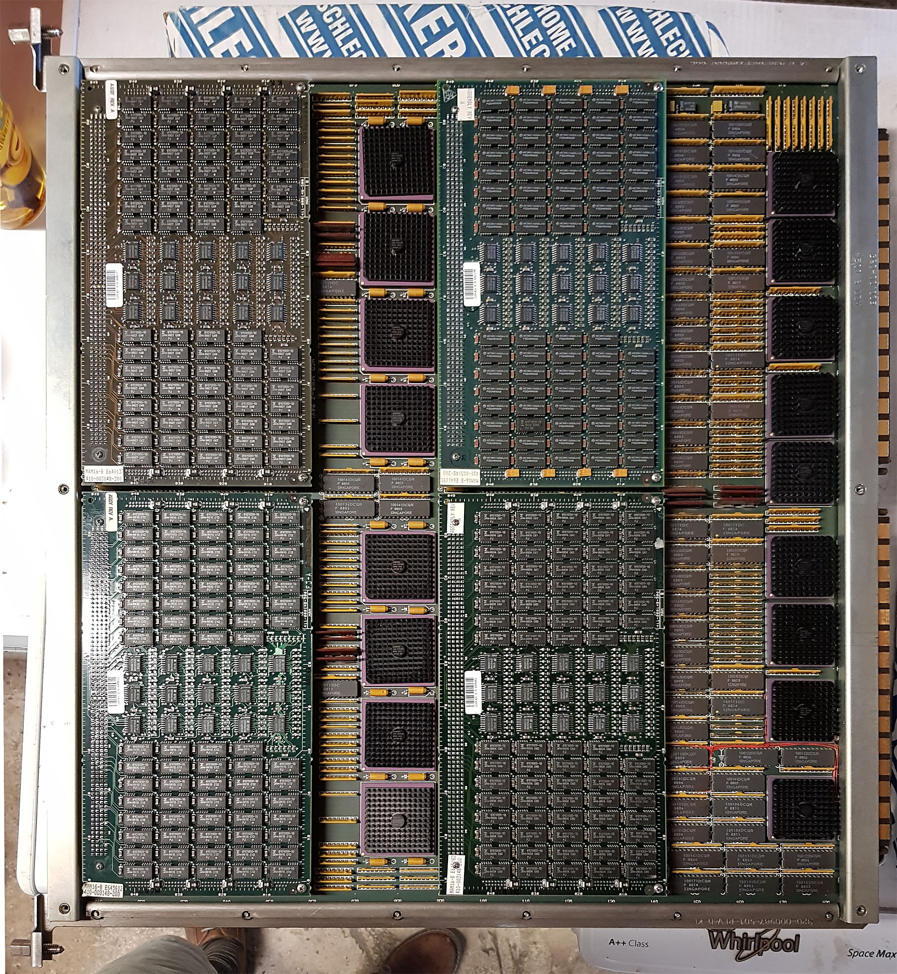
To the right of the CPX is the memory (MCM boards - Memory Control Module). This C220 has 4 boards of 64 MB each installed. A maximum of 8 boards can be installed, and I believe there are larger memory boards. The MCM contains 4 plug-in modules with the actual memory, and gate arrays to perform ECC generation and checking (7 ECC bits for every 32 data bits), as well as a 5 port crossbar so CPUs and I/O can efficiently share memory access (without the bottleneck of a bus). MCMs need to be installed in pairs (odd and even addresses).
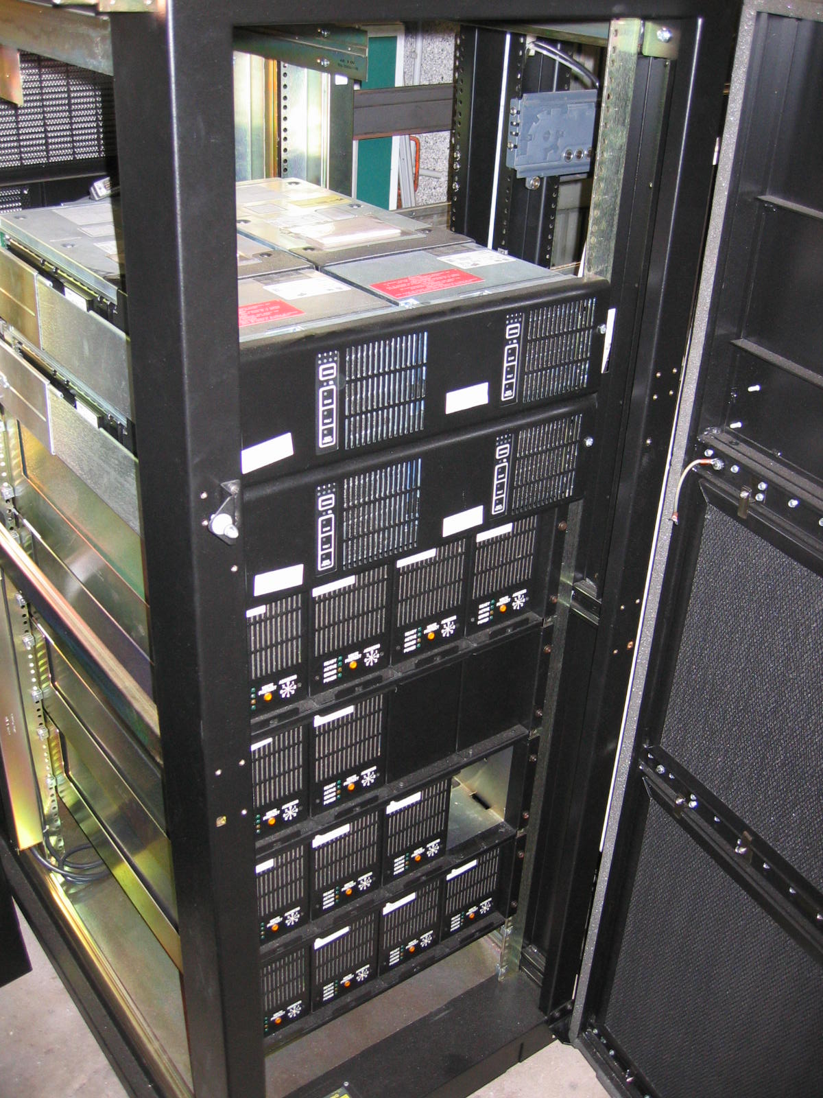
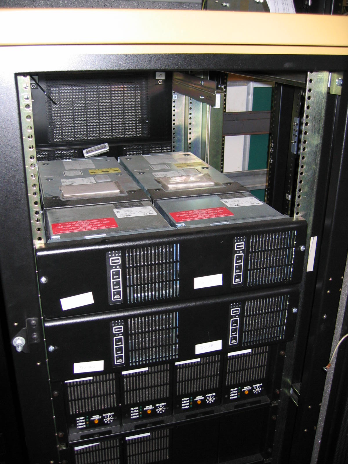
I/O Section
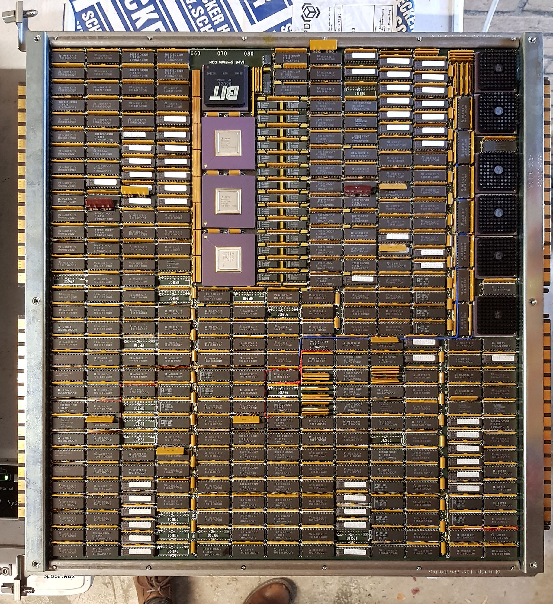
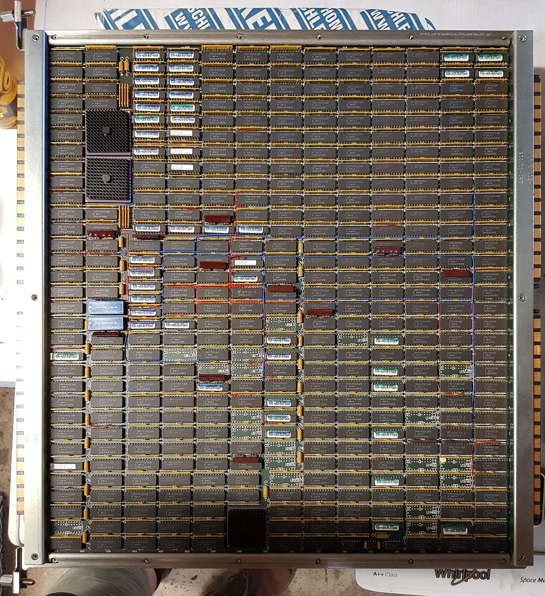
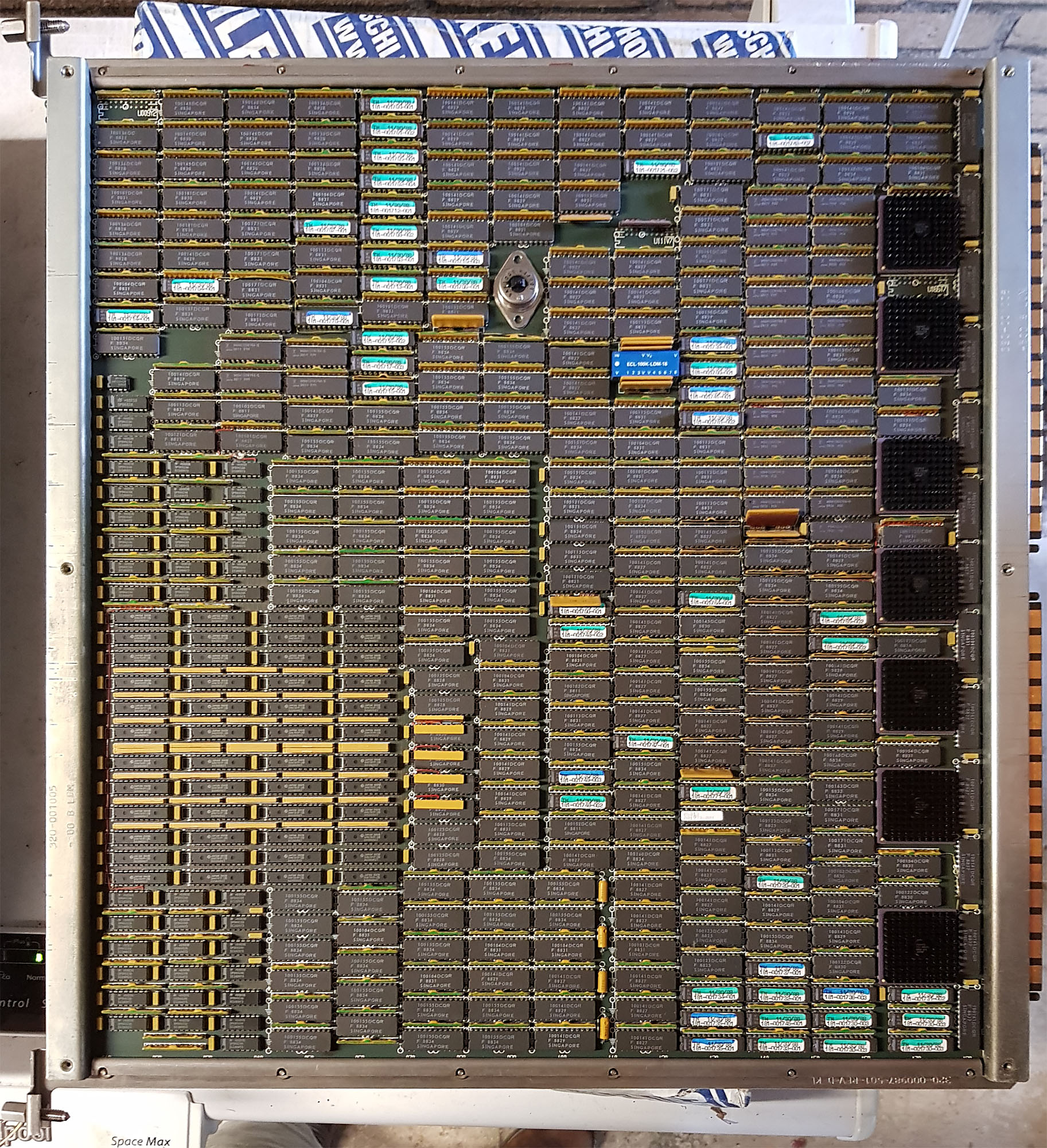
Finally, on the right side is the I/O section:
Acq C2 C220 Io 4
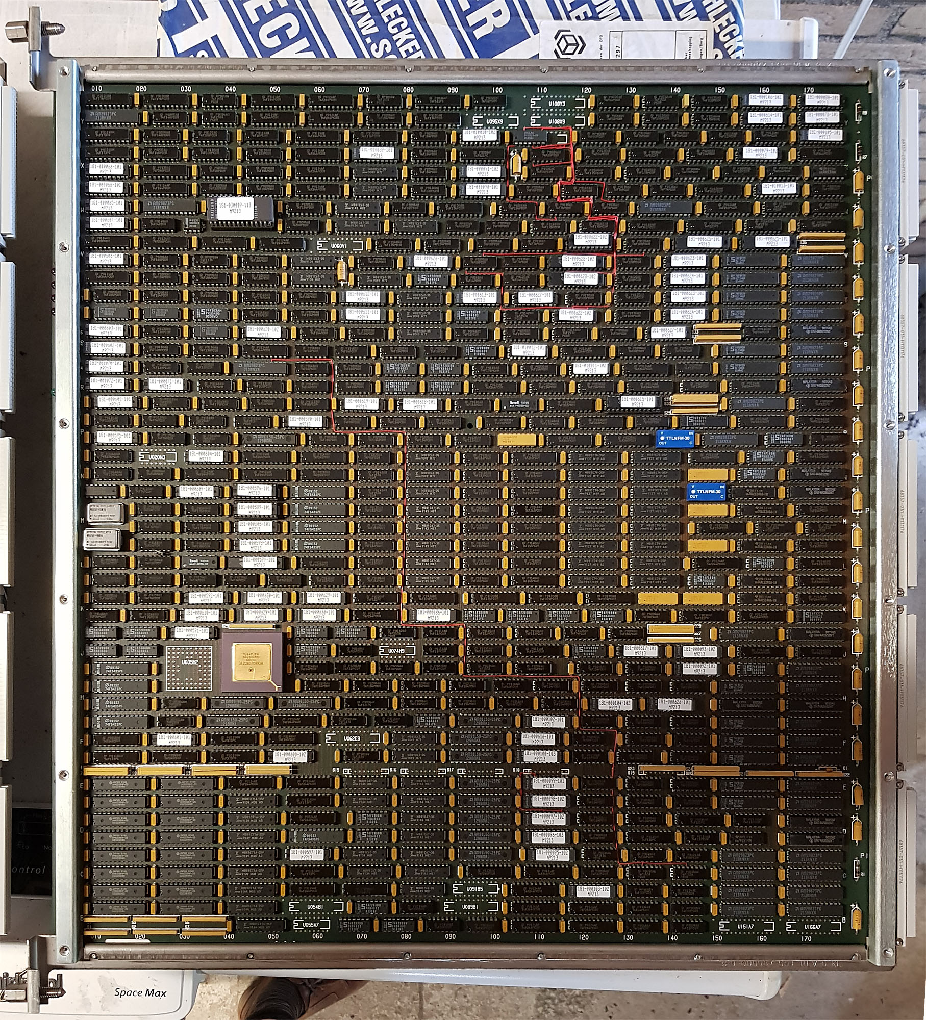
- PIA - Peripheral Interface Adapter
- IDC - Integrated Disk Channel
- RTIOP - Real-Time I/O Processor
- VIOP - VMEbus I/O Processor
The PIA is connected to one of the ports on the MCMs, and provides a PBUS, which is the same bus as the main bus that was used in the C1. Because of this, the C220 can use the same I/O controllers as the C1.
The IDC (of which there are two in this system) is a direct attachment adapter for disks (rather than going through either a Multibus or VMEbus card cage). It provides 4 disk channels, each of which supports up to 8 IPI disks. the IDC runs its own operating system on a Motorola 88000 RISC processor.
The RTIOP and VIOP each support a VMEbus chassis. The VMEbus chassis in turn supports disk and tape controllers, network interfaces, terminal interfaces, etc. The RTIOP and VIOP use a Motorola 68020 CPU.
2017-07-30 - Initial Convex C220 Checkout

After the Arrival of the Convex C220, I took some time over the course of a few days to figure out exactly what I got, and run some diagnostics. Even though none of the peripherals are here yet (they’ll arrive in a few weeks, along with the Convex C240), there are plenty of things I can do before then.
After the Arrival of the Convex C220, I took some time over the course of a few days to figure out exactly what I got, and run some diagnostics. Even though none of the peripherals are here yet (they’ll arrive in a few weeks, along with the Convex C240), there are plenty of things I can do before then.
Visual Inspection
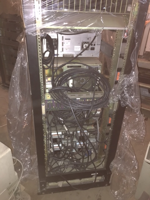
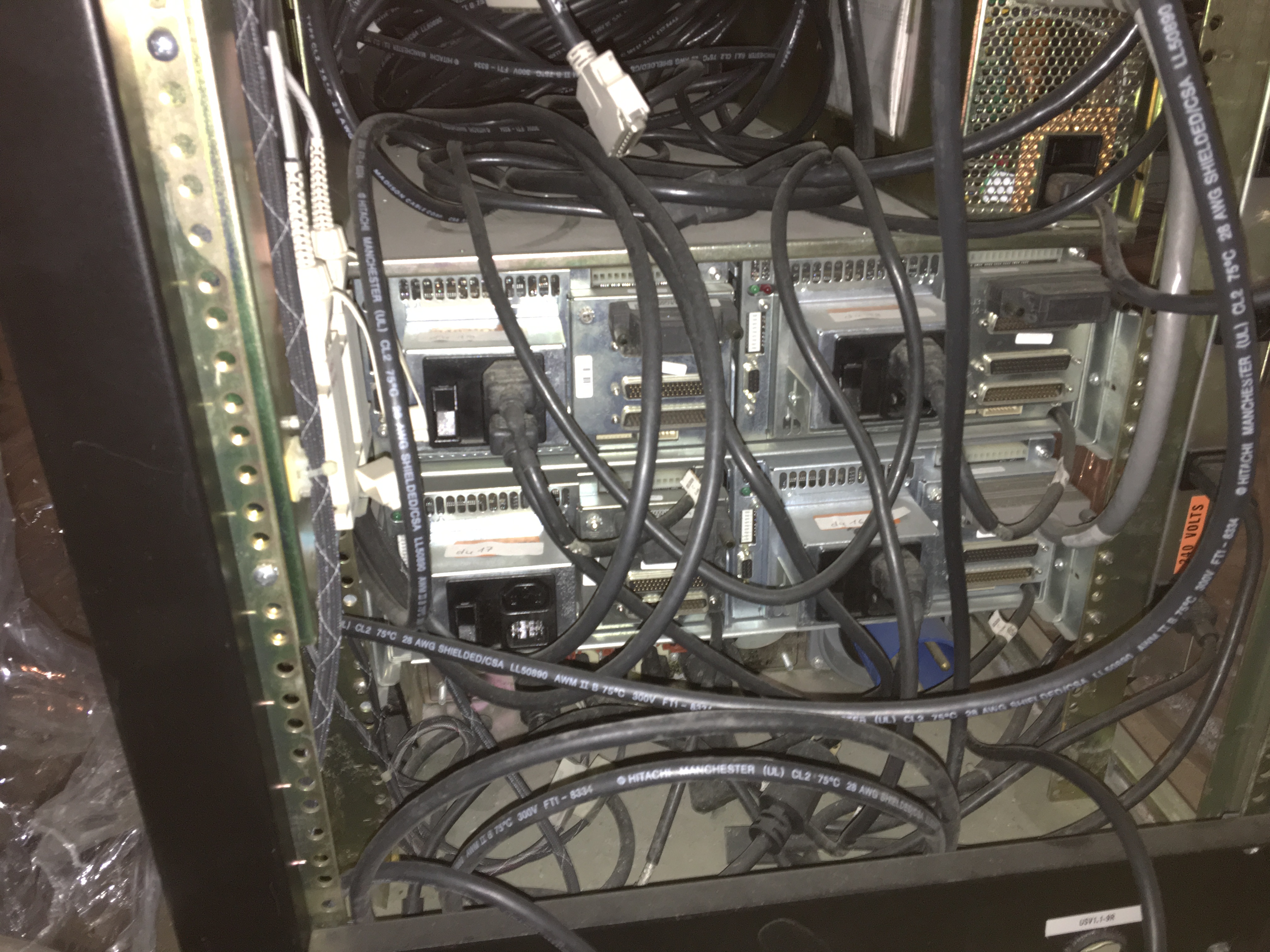
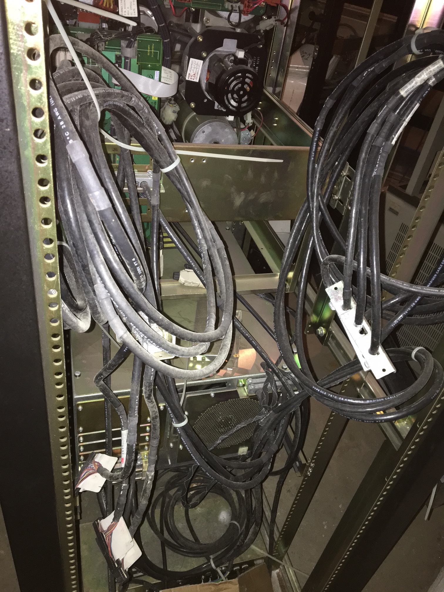
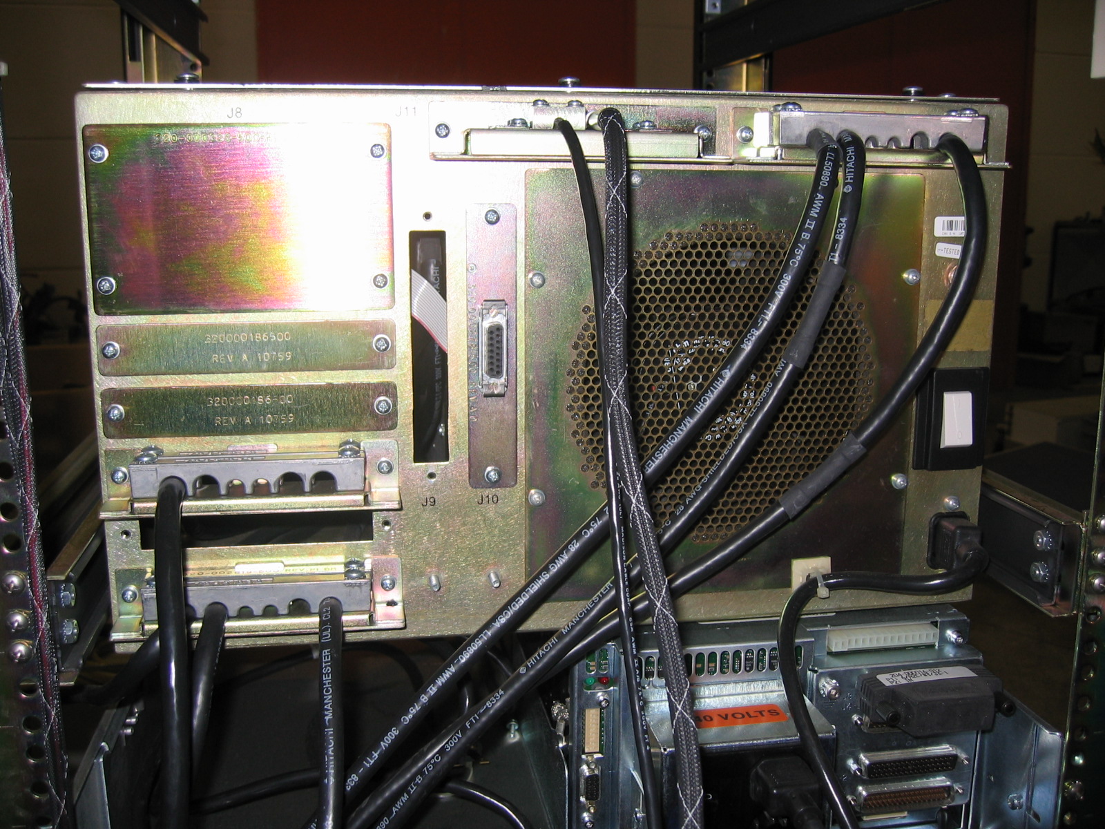
First, a visual inspection. From the back of the machine, everything that needs to be there is present, including the 8 big LH power supplies. All the cabling for the backplane is present, too, but unfortunately, when the CPU was separated from the I/O cabinets some time in the past, the 6 cables to connect to the two VMEbus I/O card cages were cut off. To avoid the risk of a short-circuit, I removed the remains of these cables from the system. Everything else looks very clean.
From the front of the machine, as soon as you open the front door, it’s apparent that the sheetmetal cover that’s supposed to cover the front of the card cage is missing. This can easily be replaced though, perhaps even with a sheet of Lexan (so you can still see the processor boards).
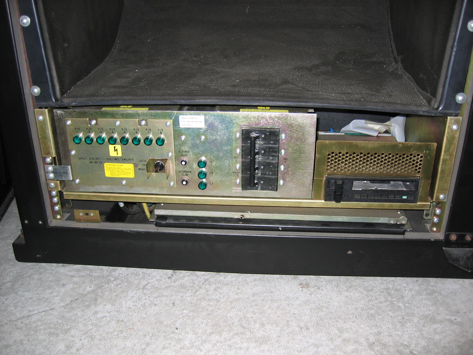
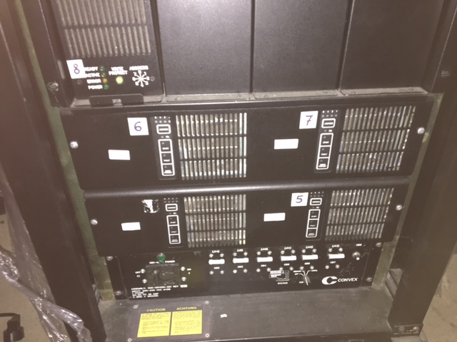
Below the main card cage, after removal of the air intake duct, the power distribution controller, systems management controller board, and service processor disk and tape drive all appear in good condition and clean.

Inside the card cage, from left to right, there are the boards for two CPUs, but the second CPU is missing the VPD (vector processor data path) board, so one complete, and one incomplete CPU. Next, The SP2 (service processor) and CPX (processor utilities) cards, and four 64MB memory boards (MCMs), for a total of 256 MB memory. 8 MCMs can be installed, and the largest boards available had 256 MB of memory each, for a maximum total of 2 GB.
On the right side of the card cage are the I/O adapters; first, the PIA, which talks to the memory and creates PBUS, the same bus used as the central bus in the Convex C1 XP. This allows the C200 series to use the same I/O adopters as the C1, which was helpful in getting the systems to market faster. Over time, newer I/O adapters were developed for the C200 series. One of these was the IDC, the Integrated Disk Channel, of which this C220 has 2. Each IDC provides 4 IPI ports, each of which supports a chain of up to 8 IPI disks. Besides the IDC’s, there are a VIOP (VMEbus I/O processor), which connects to a VMEbus card cage containing I/O controllers, and a RTIOP, which is apparently a VIOP with some extra logic in the form of a Xilinx gate array.
Finally, one other missing bit is the key that’s used to turn the machine on and off. Fortunately, the key from the C1 fits and works on this machine, too.
SPU Hard Disk backup
One of my standard procedures for bringing up a new piece of kit - especially if it’s a rare one such as this - is to first remove any hard drives from the system, connect them to a known to be good system and create an image of the hard disks. This is not always feasible, but in this case, the SPU hard disk (which contains the UNIX that runs on the service processor) is an ordinary 170MB Micropolis SCSI hard disk. It took my Linux system about two minutes to make a safety copy of the disk’s data - just in time too, as I’d find out a few hours later…
Power-on without boards
With the hard disk removed, I proceeded to remove all the boards from the card cage. This left the machine with just the power distribution controller, power supplies, fans, and SCM (system control module). The SCM is a simple microcontroller-driven board (Motorola 6805) that continuously monitors the machine’s environment (temperature, airflow), rotation speed of the fans, and power supplies. It conveys the status of the machine to the end user through a simple 2-digit hex display on the front panel.

After applying power to the machine (this involved plugging an adapter cable from 16A to 32A into the 3-phase wall outlet, plugging a 32A to 63A adapter cable into the first adapter cable, and plugging the machine into the 63A socket, all perfectly legal, and 3 x 16A should be sufficient to power the CPU), and flipping the main breaker on the machine to the on position, the display came to life, indicating “FF”. According to the legend glued to the inside of the front door, FF indicates normal status. I then turned the key from the “OFF” position to the “MAINTENANCE” position, and heard the fans whirr to life.
The front panel indicated “FF” for a little longer, as the POWER led lit up. Then, the POWER led went dark again, and the display changed to “02” - no interrupt from SP2. So, apparently, power won’t stay on unless the SCM can talk to the service processor. According to the service documentation, this did mean that all the power supply voltages where within limits for the short time it lasted. As an extra check, I applied a 2 channel oscilloscope to the -4.5V and -2V power supply rails, then turned the key. For a short time, I could observe the power supplies’ output come to life, then drop again. I then had the oscilloscope trigger and store a measurement a little after the power supplies came on, which allowed me to see how much noise there was on the power supply rails. This turned out to be very minimal, after which I repeated the procedure for +5V and -5V, and again for +12V and -12V.
Power on with minimal board set

Time to go a bit further. From the service documentation, I gathered that the minimum board set that would allow running some diagnostics on the service processor consists of the SP2, CPX, and PIA boards. I plugged these into the card cage, re-connected the SPU SCSI disk, and connected a serial terminal to the console port (9600 baud, 7-N-1, as I learned from the C1). Hooked up the oscilloscope to the -4.5V and -2V lines again, and turned the switch. The fans came on, the POWER light came on, the oscilloscope showed the -4.5V and -2V with minimal noise, and the display indicated FF - and kept indicating FF, as the SPU firmware sent the following to the serial port:
12
Convex Front Panel / Module Rev: 1.14, Version: 1 Class: 2 / CPU SN 8352
mode-of-operation = diagnostic            boot-device = disk
location-of-bootstrap = default           power-up-reboot = enable
automatic-reboot = enable                 spu-selftest = disable
os-flags = 2                              remote-port-bps = 1200
(fp)>
This is promising indeed. So, let’s try to boot…
(fp)> b
Waiting for disk ready.

SPU OS bootstrap sp2 (Generated: Wed Sep 18 11:12:58 CDT 1991)
: dk(1,0)unix

79312(4096)+10908(83408)+39262  start: 0x1000

SPU OS version 6.1.0.0

available memory = 909312 (888 Kbytes)

SPU root file system check in progress...
/dev/dk0b: 178 files 2472 blocks 1486 free
SPU mounted file systems check in progress...
/dev/rdk0f: 14 files 61 blocks 11042 free
/dev/rdk0e: 362 files 5742 blocks 34844 free
/dev/rdk0d: 1533 files 49883 blocks 31291 free
SPU file system verified
Mounted /mnt on /dev/dk0d
Mounted /hw on /dev/dk0e
Mounted /tmp on /dev/dk0f
SPU OS booted Jan 30 18:09 1970 after power up.  Freq: 50 Hz.

Sat Jan 31 01:14:52 MET 1970

(spu)> margin:   revision 5.2 (Fri Jun 18 17:48:59 1993)
Margin conditions
           clk: n +25.01 MHZ
            +5: n  +5.1  VDC
           +12: n +12.1  VDC
            -5: n  -5.0  VDC
           -12: n -12.0  VDC
            -2: n  -2.0  VDC
          -4.5: n  -4.5  VDC
So, margins appear to be well within expected limits. Like on the C1, the dshell command brings up the diagnostics shell, where you can run tests. I let the system run the tests for the boards present in the system: spu4000, cpx4000, and pia4000, these showed no errors. Then powered the system down again.
Power on with CPU and memory
Encouraged by such good results so far, I plugged in the first CPU (which is actually the second one from the left), and two of the memory boards (the MCMs need to be installed in pairs, so two boards is the minimum. I powered the system on again, and… SPU UNIX won’t boot any more. Took out the SPU hard disk a second time, and plugged into the Linux machine, and found that the hard disk had died! A good thing that I took that backup image when I did. So, I went through my shed to find a suitable SCSI disk (capable of SCSI-1), wrote the disk image to the new disk, and hooked the new disk up to the C220. After playing around with the jumper settings for a bit, SPU UNIX as booting once again!
SPU OS booted Jan 30 18:09 1970 after power up.  Freq: 50 Hz.

Sat Jan 31 01:14:50 MET 1970

Using cop to determine installed boards ...
Using scnlink to initialize scan structures ...
scnlink:   revision 5.2 (Fri Jun 18 17:49:00 1993)
Using reset_cpus to reset cpu scanability ...
reset_cpus:   revision 5.1 (Mon Apr 27 18:43:53 1992)
sysreset:   revision 5.2 (Fri Jun 18 15:49:00 1993)
LCPU_007:dcu_default:no DCU present in CPU 1.
sysreset:   revision 5.2 (Fri Jun 18 15:49:00 1993)
LCPU_007:dcu_default:no DCU present in CPU 1.
sysreset:   revision 5.2 (Fri Jun 18 15:49:00 1993)
sysreset:   revision 5.2 (Fri Jun 18 15:49:00 1993)
LCPU_007:dcu_default:no DCU present in CPU 1.
Using mcm3_config to determine memory configuration ...
mcm3_config:   revision 5.2 (Fri Jun 18 17:48:59 1993)
mcm3_config:   memory configuration:
   #   type   config
   0   mcm
   1   mcm
config_chk:   time or/and date is/are incorrect
   use the 'date' command to set time and date
   remove /mnt/chk_time.data if time and date are correct
   check service processor clock battery if time lost when powered down
   previous time: (912682056) Thu Dec  3 11:47:36 1998
   current time:  (2592993) Sat Jan 31 01:16:33 1970
config_chk:   revision 5.2 (Fri Jun 18 17:48:59 1993)
config_chk:   processor configuration:
   Processor Type: C32XX    Machine Class: 2   Serial Number: 8352
   ERROR: cpu 1 is enabled but not installed
          run disable_cpu / enable_cpu and re-run .diaginit to correct problem
-: /mnt/bin/.diaginit failed, cannot continue.
(spu)> date 9907252052
Sun Jul 25 20:52:01 MET DST 1999
(spu)> rm /mnt/chk_time.data
(spu)> disable_cpu 1
(spu)> pwrdwn
pwrdwn: Ready for power down. ^D to abort
Ok, so there’s a complaint about the time being incorrect (set to 1970), and CPU 1 not being installed (which is correct). After correcting this in the manner indicated by the output from .diaginit, the message about CPU 1 missing is gone, but the message about the clock re-appears. It seems that the clock does not survive a power-cycle. I found that this could be overcome by interrupting .diaginit with Ctrl-C as soon as it starts, then change the time and remove /mnt/chk_time.data, then running .diaginit again.
Using cop to determine installed boards ...
^C
.diaginit:   cop aborted - using old cop.out file, if any

(spu)> date 9907261117
Mon Jul 26 11:17:01 MET DST 1999
(spu)> rm /mnt/time
rm: /mnt/time nonexistent
(spu)> rm /mnt/chk_time.data
(spu)> .diaginit

Using cop to determine installed boards ...
Using scnlink to initialize scan structures ...
scnlink:   revision 5.2 (Fri Jun 18 17:49:00 1993)
Using reset_cpus to reset cpu scanability ...
reset_cpus:   revision 5.1 (Mon Apr 27 18:43:53 1992)
sysreset:   revision 5.2 (Fri Jun 18 15:49:00 1993)
sysreset:   revision 5.2 (Fri Jun 18 15:49:00 1993)
sysreset:   revision 5.2 (Fri Jun 18 15:49:00 1993)
sysreset:   revision 5.2 (Fri Jun 18 15:49:00 1993)
Using mcm3_config to determine memory configuration ...
mcm3_config:   revision 5.2 (Fri Jun 18 17:48:59 1993)
mcm3_config:   memory configuration:
   #   type   config
   0   mcm
   1   mcm
config_chk:   revision 5.2 (Fri Jun 18 17:48:59 1993)
config_chk:   processor configuration:
   Processor Type: C32XX    Machine Class: 2   Serial Number: 8352
   CPU         0   1
   installed:  X
   available:  X
Initializing system config files
sysreset:   revision 5.2 (Fri Jun 18 15:49:00 1993)
mminit:   revision 5.2 (Fri Jun 18 17:48:59 1993)
mminit:   generating PCM
mminit:   initializing PI, CU, and SP PCMs:   0:00:00   0:00:05   0:00:10   0:00:10   0:00:10

Main memory size:  134217728 bytes - 131072 K - 128 Meg

pair  allocated 16 meg PCM blocks, from a system perspective
 0      0   1   2   3  16  17  18  19
 1
 2
 3

mminit:   interleave set to 8-way
Initialization completed.
Running Memory Diagnostics
Running the memory diagnostics revealed an error on one of the memory boards, in the crossbar switch that connects the CPUs and I/O adapter to the memory modules:
*****  Sun Jul 25 21:15:27 1999  *****
Test:    mem4000.t  1.17   Class: 1    Subtest: 200 1.5   Count: 1    Error: 0
Failed:  Crossbar write/read latching

Pattern: Ramp up data. Next test type: port E & port A.
Slot: me0
xbar: 0 port: 0

 FAIL    OFFSET/
 TYPE     ADDR      EXP       ACT     COMMENTS
Data              00000001  00000010 initial read ptr failure

Test 'mem4000.t' failed
So, I unplugged that memory board and replaced it with another one. The test now fails later, when it first tries to use the CPU. I realized I had not initialized the CPU before running the mem4000 test, which is a prerequisite. So, reboot, and after .diaginit, run initall:
(spu)> initall
System Initialization
config_chk:   revision 5.2 (Fri Jun 18 17:48:59 1993)
config_chk:   processor configuration:
   Processor Type: C32XX    Machine Class: 2   Serial Number: 8352
   CPU         0   1
   installed:  X
   available:  X
sysreset:   revision 5.2 (Fri Jun 18 15:49:00 1993)
margin:   revision 5.2 (Fri Jun 18 17:48:59 1993)
Margin conditions
           clk: n +25.01 MHZ
            +5: n  +5.1  VDC
           +12: n +12.1  VDC
            -5: n  -5.0  VDC
           -12: n -12.0  VDC
            -2: n  -2.0  VDC
          -4.5: n  -4.5  VDC

Loading control stores
Opened file /mnt/usr/ucode/us.200.wcs  Rev 11.10
Opened file /mnt/usr/ucode/sr.wcs  Rev 11.4
Opened file /mnt/usr/ucode/ua.wcs  Rev 10.10
Opened file /mnt/usr/ucode/ul.wcs  Rev 10.3
Opened file /mnt/usr/ucode/um.wcs  Rev 10.6
Opened file /mnt/usr/ucode/vd.200.wcs  Rev 10.1
Loading Scalar Control Store: us                0:23
Verifying Scalar Control Store: us              0:17
Loading Scalar Control Store: sr                0:26
Verifying Scalar Control Store: sr              0:28
Loading Vector Control Stores: ua ul um vd              0:06
Verifying Vector Control Stores: ua ul um vd            0:08

sysreset:   revision 5.2 (Fri Jun 18 15:49:00 1993)
sysreset:   revision 5.2 (Fri Jun 18 15:49:00 1993)
mminit:   revision 5.2 (Fri Jun 18 17:48:59 1993)
mminit:   using PCM from /mnt/boot_db
mminit:   initializing PI, CU, and SP PCMs:   0:00:00   0:00:05   0:00:09   0:00:09

Main memory size:  134217728 bytes - 131072 K - 128 Meg

pair  allocated 16 meg PCM blocks, from a system perspective
 0      0   1   2   3  16  17  18  19
 1
 2
 3

mminit:   interleave set to 8-way
mminit:   using CPU 0 to initialize memory:   0:00:00   0:00:05   0:00:10
+++>
<Mon Jul 26 11:23:00 1999>   mminit(108):../errlog.c:104
SW Error (DiagER217): cpurequest () failed

mminit:   error:   hard error occurred

****
hard_logger:   revision 5.2 (Fri Jun 18 17:48:59 1993)
hard_logger:  invoked for system serial number 8352
ME0/MCM: hard_err is not set
ME0/MCM: Soft errors disabled.
ME0/MCM: soft_err is not set
MO0/MCM: hard_err is not set
MO0/MCM: Soft errors disabled.
MO0/MCM: soft_err is not set
CPX: Hard error detected.
CPX: [#412] Comm register parity error.
        Addr <9..0> = 000, Synd = 04

CPX: soft_errs is not set
CPX: Hard error detected.
CPX: [#412] Comm register parity error.
        Addr <9..0> = 000, Synd = 04

CPX: soft_errs is not set
PIA: hard_err is not set
PIA: softerr is not set
ASA/ASP: hard_err is not set
DCA/EDC: hard_err is not set
IPA/IPP: hard_err is not set
VCA/VPC: hard_err is not set
VCA/VPC: softerr is not set
VDA/VPD: hard_err is not set
  0:00:35   0:00:35

+++>
<Mon Jul 26 11:23:26 1999>   mminit(108):../mminit.c:654
SW Error (DiagER210): mminit failed

mminit:   initialization by CPU 0 failed

****
Initialization Aborted
So, a parity error is detected by the CPX, which causes mminit to fail. According to the maintenance documentation, the error can be on the ASP or CPX board, or on the backplane. There was also a set of suggested diagnostics to run for the ASP and CPX boards. The cpx4000 subtests for this error all check out fine, but I can’t run the cpu4232 subtests, because those need main memory to be initialized. So, after I get back from vacation, I still have some sorting out to do.
2017-08-31 - Convex C240 Arrived
Last Tuesday, Andreas, a friend from Germany, arrived to deliver the Convex C240. Along with the C240 came all the I/O cabinets and devices for the Convex C220, as well as a lot of spare parts (boards, PSU's, drives).
Last Tuesday, Andreas, a friend from Germany, arrived to deliver the Convex C240. Along with the C240 came all the I/O cabinets and devices for the Convex C220, as well as a lot of spare parts (boards, PSU's, drives).
Andreas brought his family, and we had a nice evening together.
Acq C2 C240 1

Acquisition Record
Acquired from: Andreas Holz